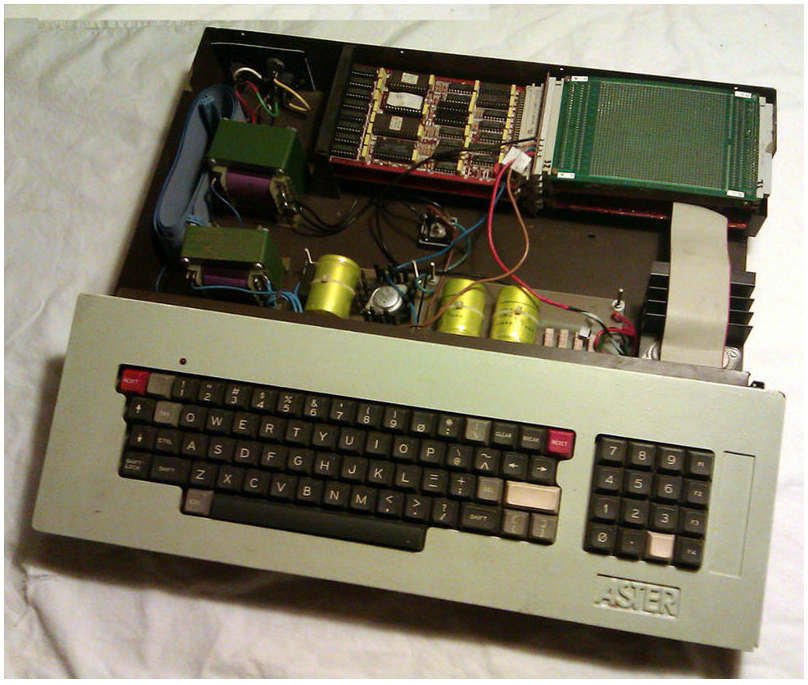
The image is from the school leaflet. Note the discrete flatcable between computer enclosure and keyboard. The old model VDU-card has a VHF/UHF modulator.
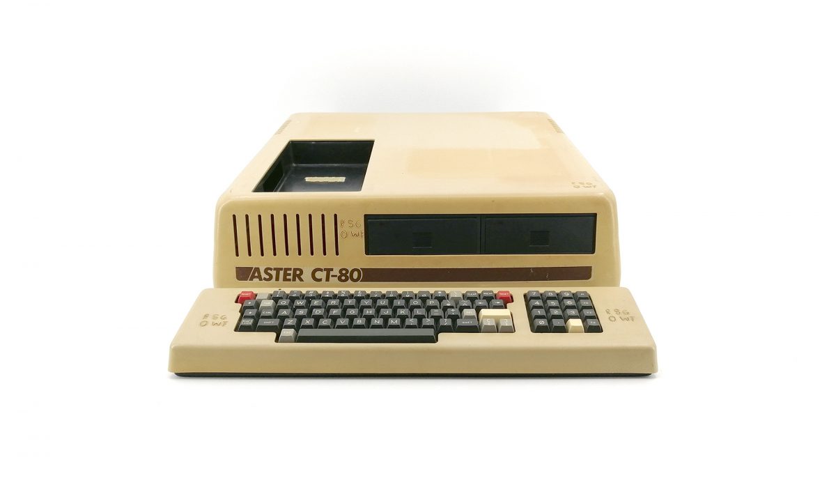
Note the new style keyboard and space for a cassette recorder on top. The keyboard is connected with a thick round cable (containing the same original 20 conductors).
Presumably the first model was a bare Euro card rack with a power supply and four or more cards. The keyboard is connected to one of the cards with a 20 conductor flatcable. For the school situation the whole rack was probably bolted student-proof to the desk.
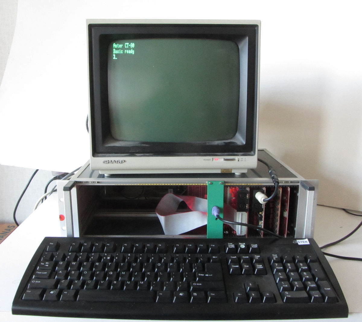
In this instance the original missing keyboard is replaced with a PS/2 keyboard and converter. More info on this on: Hackaday and Github.
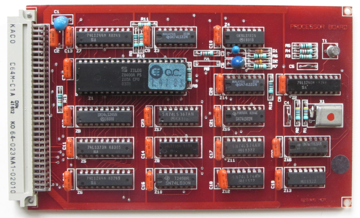
The CPU board containedthe processor, some bank-switching logic and a way to switch the processor clock. Depending on the chosen crystal frquency, the CPU clock is 1.77/3.548 MHz (14.1926 MHz crystal) or 2/4 MHz (16 MHz crystal). The 1.77 MHz mode made the computer compatible with TRS-80 M1 timing and cassette tapes.
The bankswitching logic allowed the use CP/M and compatible operating systems.
More info on this board is in this partial translation of the preliminary manual.
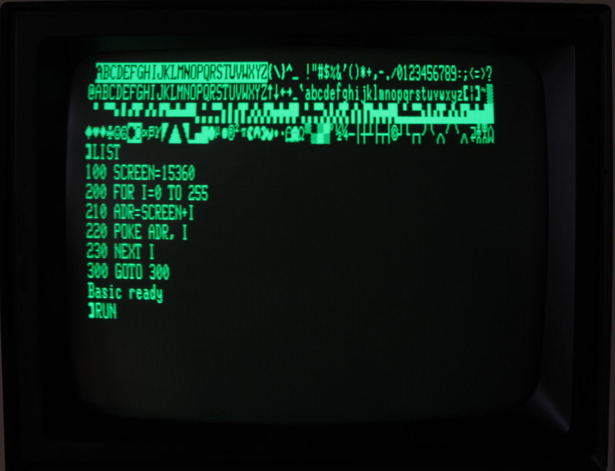
At high clock speed there could be issues when slow EPROMs were used. The Aster could copy the BASIC ROM to RAM at the same memory location and swap the slow ROM out. BASIC then ran from fast RAM.
The control of port FEh on the memory map is quite confusing. In port FEh and Memory Map a breakdown of relevant settings and the effect on the memory. This is made easy with the Z80 exerciser.
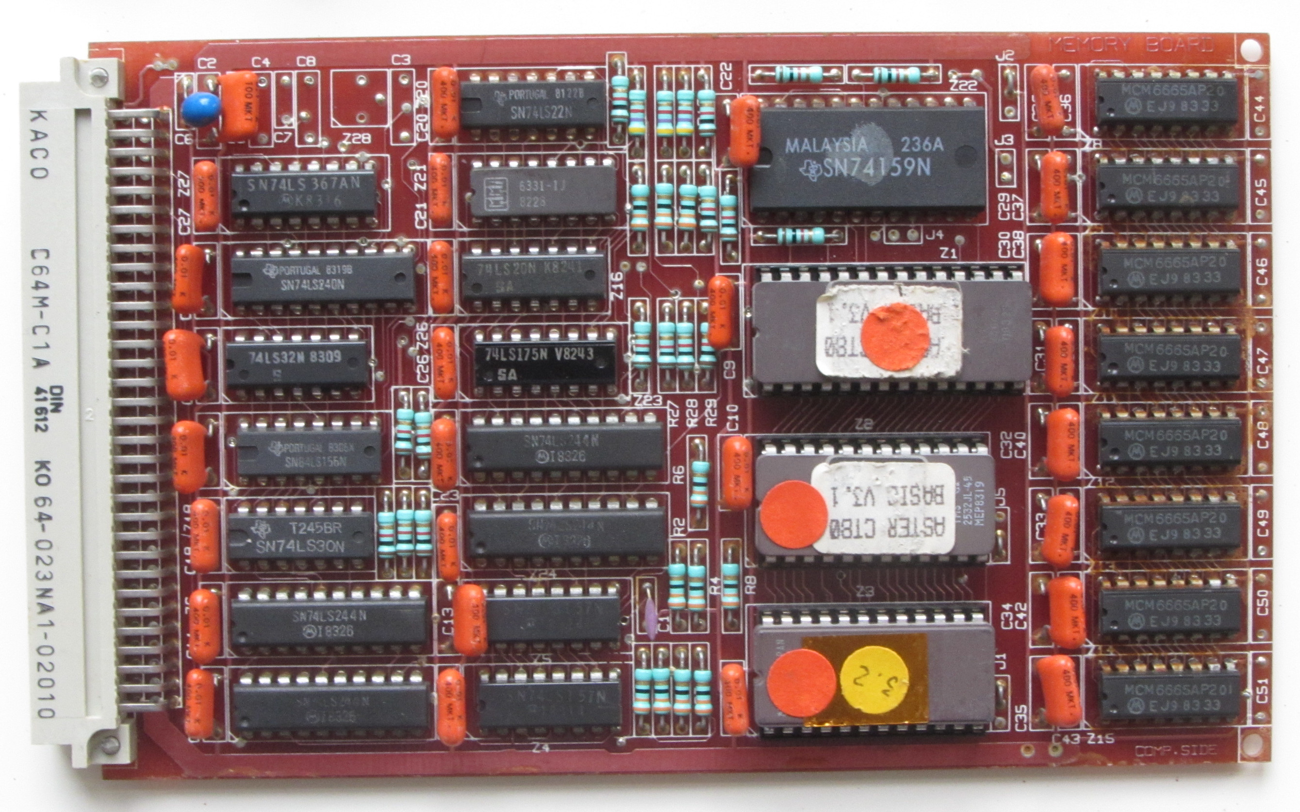
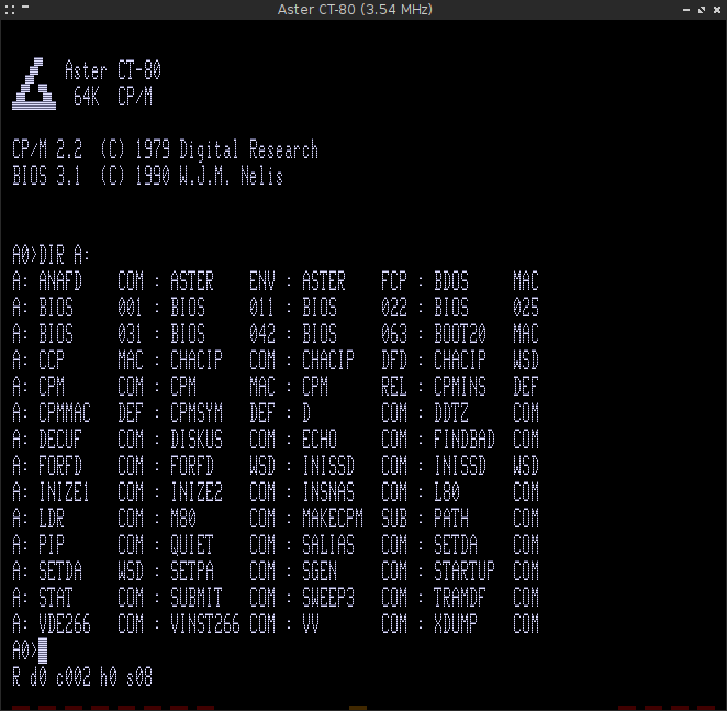
This board contained 64kByte dynamic RAM, Microsoft Basic (4 kbyte & 8 kbyte ROMs) and a special boot-ROM (2 kbyte). This boot ROM selected the boot mode and code to initialize the CRT chip on the Video board.
More info on this board is in this partial translation of the preliminary manual. The MAP-ROM file contains the contents of the MAP-ROM.
The MEMORY BOARD alse generates address decoding signals used on other boards; Video (31a) to select video RAM, Keyboard (24c) to select the keyboard area and I/O (27a) to select the Floppy Disk Controller registers, Drive Select and Density configuration.
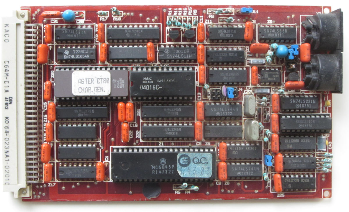
The video board is one of the departures from the TRS080 Model 1. The latter only has a 64 characters by 16 lines display, the Aster added an 80 character by 25 lines mode. This was done by replacing the discrete TTL-video chain by a 6845 CRT.
There were several variants of this board, at least one with a VHF-modulator, and one without. All boards had two video outputs. For the school situation one was wired to the teacher desk, allowing her/him to monitor the progress on all student computers, one at a time
The DIN-connectors both support a light-pen signal, on a pin not used for video output.
It is possible to operate the 80 character wide mode in TRS-80 mode, but because only 1 kByte RAM of memory can be addressed in this mode, you end up with 12 and a half line.
More info on this board is in VDUboard.txt.
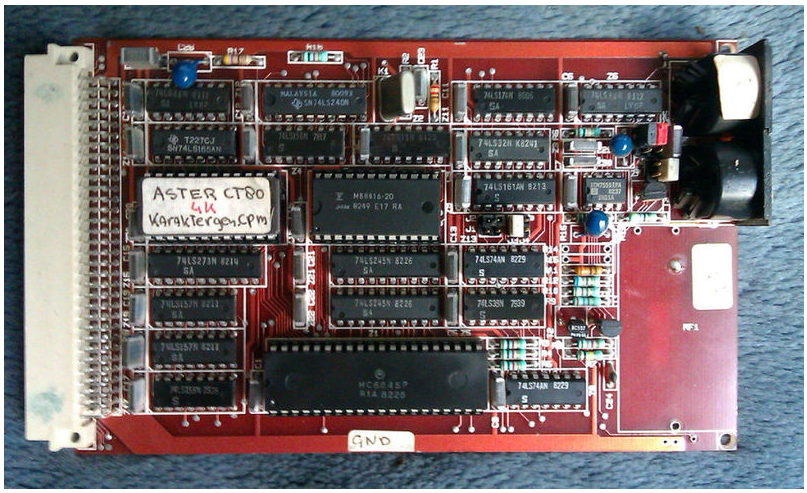
Here is an image of a previous version of the VIDEO BOARD. It had space for a VHF modulator to connect it to a television. It only had a single clock, meaning the 64x16 screen was actually smaller than the 80x25 screen. The character generator ROM only contains a single set.
The character set was slightly different from the TRS-80.
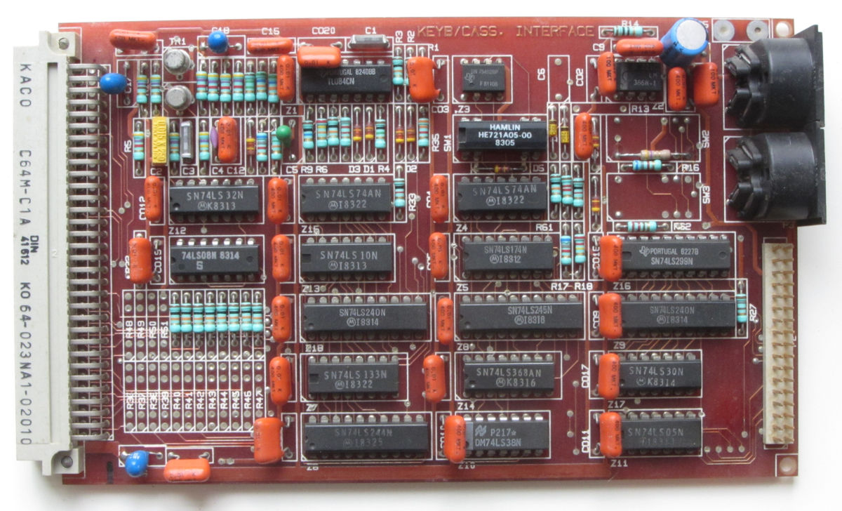
This board has logic to connect a passive 8x8 keyboard matrix, similar to the TRS-80 M1. The latter had some buffering logic on the keyboard PCB, the Aster variant was passive, only switches and a pull-up resister network. The buffering was done on the Eurocard. The keyboard logic optionally included a way to generate interrupts on keystrokes.
The cassette circuit allows two cassette players to be connected, but for a school situation, it was repurposed for a simple network, where a teatcher could send a program too all student computers. This after all students entered the 'CLOAD ""' command first.
The keyboard had some interesting addition to the TRS-80 Model 1 layout. Esc, Control, [, ], {, }, F1-F4, double Reset keys and a separate rightShift key. The latter was not compatible with the TRS-80 Model 3 layout.
More info on this board is in this partial translation of the preliminary manual.
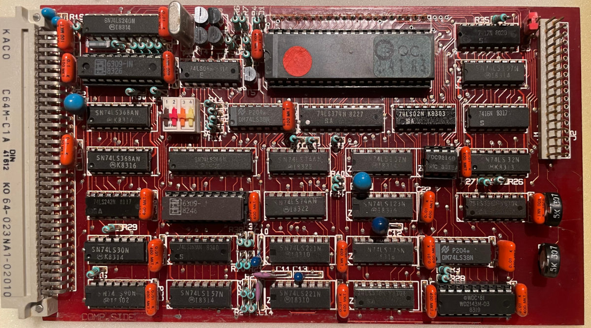
The floppy controller board had the doubler logic integrated, so it could run the standard, single density based operating systems and the more modern double density systems. To cram two controller chips and the data separator logic on an Eurocard, one floppy controller chip is located at the back of the board. An original implementation of 'double-sided'.
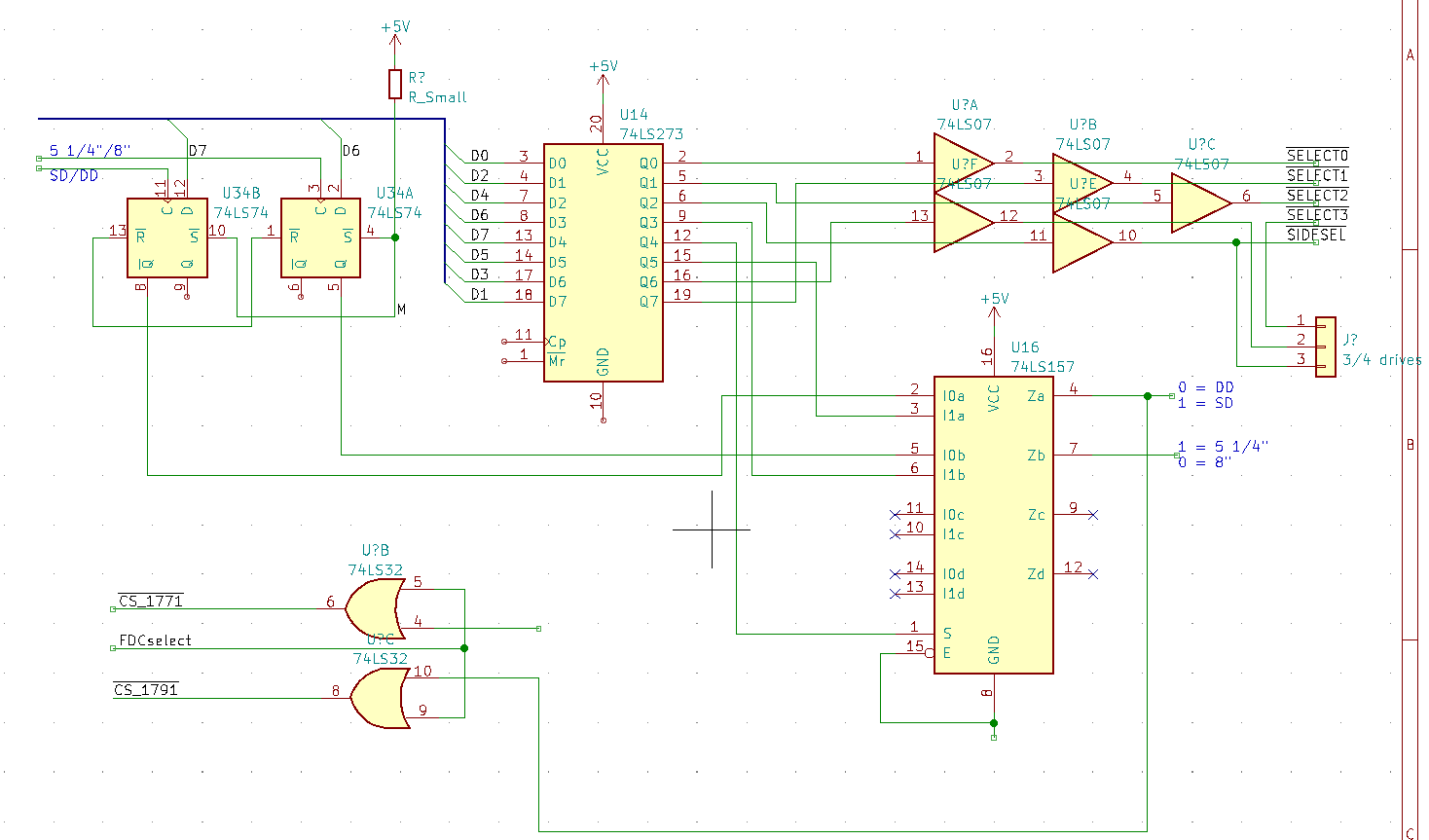
The FDC board uses two 74LS471 PROM (256 * 8, superceded by TBP28L22)) for I/O decoding. Boot configuration (drive size and density) is done with bits 6 and 7 of port 37ECh. With a preset of the flip-flops address by these bits double density or 8" boot can be selected.
More info on this board is in FDC Board description. Part of the schematic: Disk drive select plus density drive size configuration.
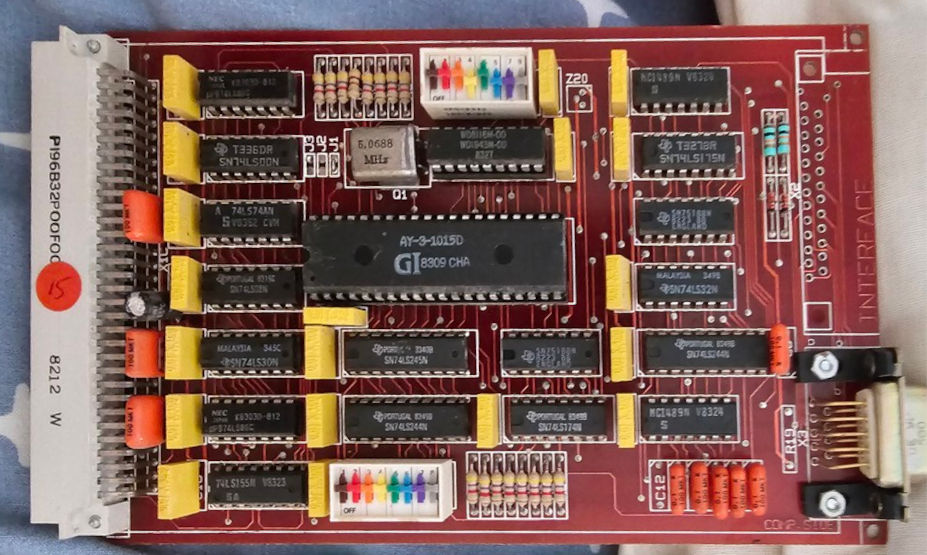
TRS-80 Model 1 compatible serial interface. (Image borrowed from D. Pennings www.retromuseum.nl)
.The 9 pin connector pinout is for modem use and not compatible with the later IBM AT 9 pin serial connector.
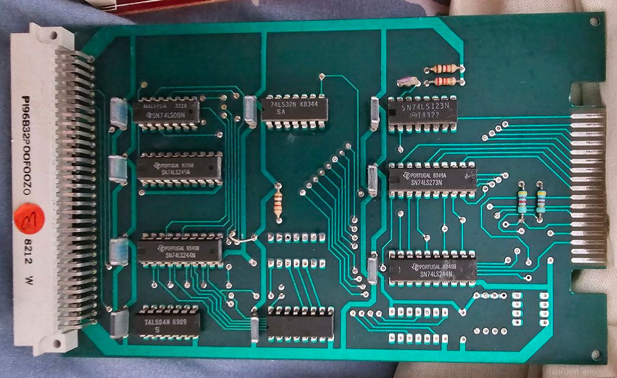
TRS-80 Model 1 compatible printer interface. (Image borrowed from D. Pennings www.retromuseum.nl)
.