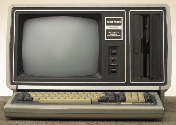
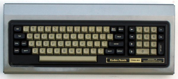
After the instant succes of the Model I, Tandy realized it was not much of a business computer with only a cassette recorder as storage medium (floppys came later). So a real business computer was developed, which became the Model II. Quote from CREATIVE COMPUTING VOL. 10, NO. 11 / NOVEMBER 1984 / PAGE 292: The original TRS-80 was a limited machine with 4K of memory, upper case only, a restricted Basic, and casette storage. Even with the disk system and extended Microsoft Basic, the improvement was not enough to make it a serious contender in the business market. Tandy executives recognized that, and on May 30, 1979, the TRS-80 Model II, a state-of-the-art business machine was announced. It had dual 8" disk drives and might have taken the business market by storm had it not had a nameplate reading "Radio Shack."
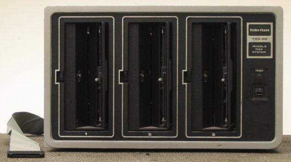
For applications which needed more space than was available on the System disk, the Disk System was the proper extension. Sold with either one, two or three disks installed, it is a flexible, but pricey option. The drives are Magnetic Peripherials Inc. (CDC) MPI9404. The whole box weighs 35 kg (77 lb).
The CPU card contains three Z80 peripherials (DMA, CTC, SIO/0) and the FDC card contains a PIO. As the interupt chain is standard limited to four devices because of delays, Tandy engineers added some external logic to allow a larger chain. The solution is simply a 74182 ROM and some inverters. A similar circuit in the Zilog documentation allows up to 30 devices in the chain.
There were several boot ROM variations for the model II. Marmotking
made a collection of these and I disassembled some. Here is a ZIP with the result.
My conclusions so far:
cpu_c8ff.bin/.hex - 432F - No HDA support (Version 1, no date)
cpu_2bff.bin/.hex - slightly different HD boot code (compared to 1bbe/2119) (Version 2, 81-07-29)
cpu_2119.bin/.hex - Identical to 1bbe (8 bytes different in the unused area) (Version 3, 82-05-07)
cpu_1bbe.bin/.hex - Identical to 2119 (8 bytes different in the unused area) (Version 3, 82-05-07)
cpu_fc86.bin/.hex - U54 in M12. Very similar to 9733, but with different ROM checksum
                    (Version 4, 82-11-18)
cpu_9733.bin/.hex - Resets DMA, CTC SIO, no ROM checksum (Version 5, 83-07-29)
Technical Bulletin II:33 also lists five boot ROMS (with two variations), but with different checksums. These can be checked with the MEMII/CMD program.
Eric Smith recreated boot ROM assembly files with superior comments.
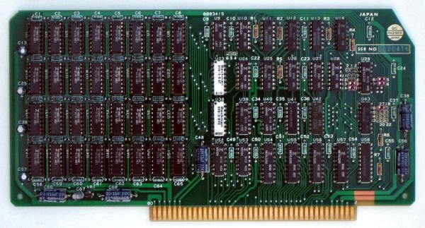
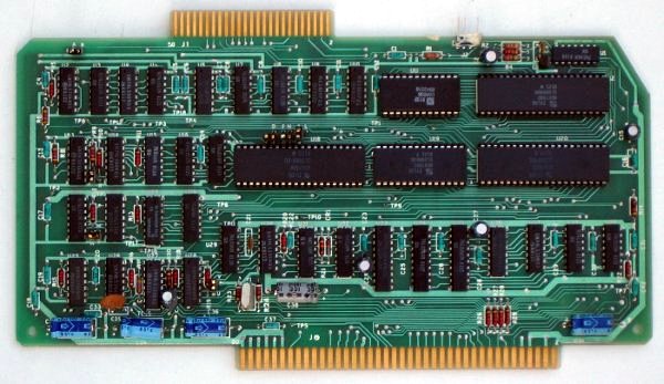
The memory can theoretically be expanded to 512 kByte using 8 boards. But in practice you are limited to 320 kByte because only four slots are available. The Pickles & Trout CP/M can see and test the memory above 64 kByte. TRSDOS 2.0a will look no further than 64 kByte. TRSDOS-II required 64+16 kByte RAM.
The page size is 32 kByte. Page 0 is mapped at 0000h-7FFFh and the pages 1 to 15 are mapped to 8000h-FFFFh. Switching pages is done with the lower nibble of I/O port FFh. Bank F (and mirrored at E) is used by the 16 kByte on the Hard Disk Interface Board.
The Technical Reference Manual suggests setting J8-J12, J9-J13 and J19-J27 for the standard 64k card (page 78), but this doesn't work in my Model II. My working 64 kByte card has J9-J13, J10-J14, J15-J18, J16-J17 and J26-J27 set. This only partially matches with the table on page 77.
From Technical Bulletin II-002:
DISCUSSION: There are three possible memory board configurations
for the Model II. A 32K Ram board, a second 32K Ram board to upgrade from
32K to 64K Ram, and a single 64K Ram board. Jumper configurations are
different for each board.

PROCEDURE: The correct jumper configurations are:

First 32K Memory board:
16-17  Selects the first 16K of the base page
15-18  Selects the second 16K of the base page

Second 32K Memory board:
26-27  Enables the next jumpers on page 1 of the memory map
9-11   Selects the first 16K of page 1
10-12  Selects the second 16K of page 1

64K Memory board:
16-17  Selects the first 16K of the base page
15-18  Selects the second 16K of the base page
26-27  Enables the next jumpers on page 1 of the memory map
9-13   Selects the first 16K of page 1
10-14 Selects the second 16K of page 1

The following jumpers are required to be installed on all memory boards.
1-2  Pulls up an input to U27 that was floating
5-6  Pulls up an input to U9 that was floating
Use MEMII Diagnostic to check each memory board for correct jumpering and
proper operation.
CONTROLLER
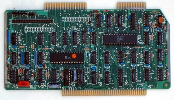
The floppy format used for TRSDOS 2.0 is single-sided, double-density, 77 tracks, 26 sectors per track. Track 0 is single density with 128 byte sectors. Other tracks are 256 bytes per sector. Interleave is 5 (with sector order: 1, 6, 11, 16, 21, 2, 7, 12, 17, 22, 3, 8, ...). TRSDOS II used 512 byte sectors for track 1 and up.
BTW, this board is different from the one shown in the Technical Reference Manual. It uses a separate cable for the internal drive, and has connections for two 34 pin headers, one looks like a 5 1/4" floppy connector.
This is the "Late Design FDC" board, requiring no loopback plug when the Model II is operated without Disk Station. The earlier cards (REV A, B and C, see the Model 16 page) does need the loopback plug.
Someone at Vintage Computer Forums kindly provided info on the terminator, which is actually a loopback connecting resistors at the internal floppy drive.
From Technical Bulletin II-019:
DISCUSSION/PROCEDURE:  The Late Design FDC board is very different
from the early style FDC board. It incorporates the Western Digital 1691
Floppy Support Logic and the 2143 four phase clock chips. Variable
precompensation and a software reset are also used. Jumper options are
available for different modes of operation. when this board is installed
the external terminator plug is not used. Also, if an expansion bay is in
the system it does not have to be powered up to use the computer.
There are a number of operating systems for the Model II family of computers (adapted from http://home.claranet.nl/users/pb0aia/cm/modelii.html):
| TRSDOS 1 | Obsolete. 1.2a was the latest version |
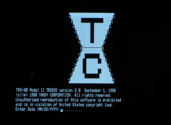
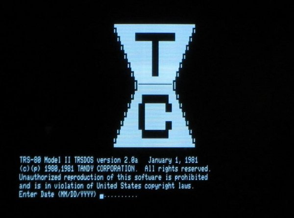
| TRSDOS 2.0a | For the full height single sided drives, basically the Model II version. Originally known as 2.0 |
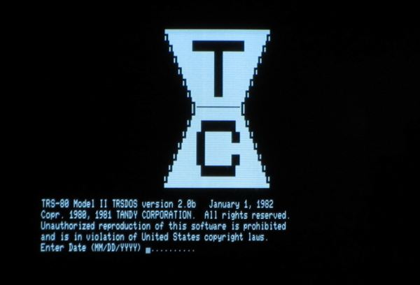
| TRSDOS 2.0b | For software compatibility of TRSDOS 2.0a, but for thinline drives, for model 12 and 16B |
| TRSDOS II | 4.0 was for Model II Hard Disk support. Adds hard disks as drive 4, 5, 6, 7. Version 4.1 was for the Model II/16 with harddisk and 68000. TRSDOS-II requires 64+16 kByte RAM. This can be in board (M12 and 16b), an extra RAM card, the harddisk interface card or the 68000 RAM card. The last main branch TRSDOS II versions were numbered 4.2.x, with 4.2.9 the latest. There was a 4.3(11i) release for systems with ARCNET. A 4.4 was produced, but not released via retail. |
| TRSDOS 16 | Uses the 68K board, single user OS |
| TRS-XENIX 1.03 | For the 68K boards, Enhanced Model II, Model 16 |
| TRS-XENIX 3.01 | For the Tandy 6000 or 16B with upgrade |
| LS-DOS 6.3.1 | Could interchange data and most programs with the Model IV |
| DOSPLUS-II | The DOSPLUS version for the Model II |
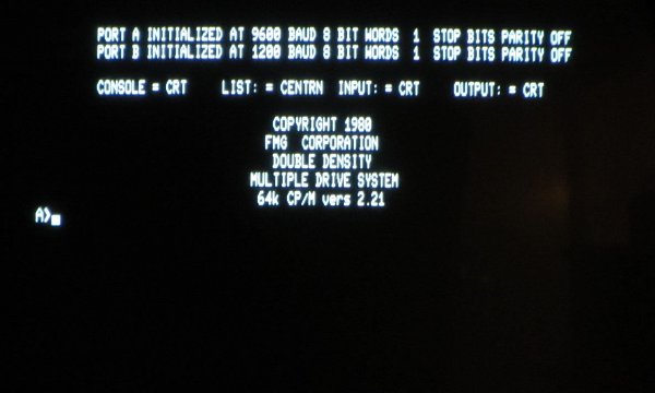
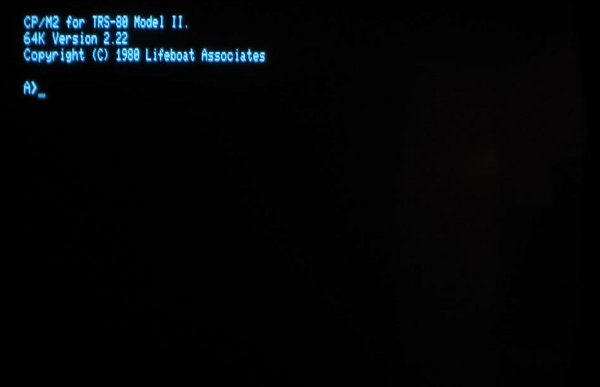
| CP/M 2.2 | The standard CP/M was available from different vendors for the Model II; Tandy, FMG Corporation, Lifeboat Associates, Pickles &Trout, ... |
| CP/M Plus aka CP/M v3 | Available in a banked and unbanked version for the II and 12 |