The Radio Shack TRS-80 MODEL II MICRO COMPUTER
Checking and fixing the Model II.
Phase 1
Soon after getting the machine, I wanted to see if it still worked. The previous owner, which had the machine since the early 80's said he tried it some years ago, and then it still worked. The machine came with the impressive (both size and weight) three floppy disk system.
But knowing 30 year old components might fail, I tried to be cautious. The Technical Reference Manual contained some troubleshooting tips, like making a minimum load for the power supply. That would really be wise; get the power supply (early switching one from Astec), connect a load and check the voltages. Only then connect it to the computer.
After opening the case, I found several reasons to change the plan.
- The basic construction was clean, although you need special extra long screwdrivers to reach some important screws, like those from the power supply/monitor board, the card cage or the floppy drive. And more than a few wires were neatly strapped afterwards to convenient posts, connecting everything with almost everything. Getting the power supply out would be a major task.
- The cardcage was connected to the power supply with an impressive 15 wire connector. Building a neat load would not only need several large resistors, but also another plug. Soldering wires directly to the board would be a cheap, but not so neat workaround.
- The diagram of the power supply showed a crowbar circuit on the 5V lone and fuses on +24V, +12V and +5V. This would provide some safety in case of a malfunction.
 So I decided for a short switch on and see what would happen. I noticed one of the primary filter capacitors had already exploded and had leaked. The other capacitor, behind the coil looked ok, but was of the same brand so also suspect. Not only were both almost 30 years old, but dimensioned for 220V, while we have 230V nowadays.
Indeed, when switching on, the fan came to life, as did the power LED, but also the second filter capacitor. Some fireworks so I switched off. Having enough adventure for the day, I decided to replace them both with new ones. Further in the filter were two smaller ones of the same type and brand, but they looked ok, and had lower capacitance so I left them in place (lower capacitance can mean higher margins).
Replacing the capacitors without getting the complete supply out was doable because they were on the top of the board. By loosening top half of the board, there was enough space for the soldering iron.
Phase 2
 With the new capacitors in place, I tried again. Not yet with the external disk system. This means I didn't had the proper termination, but also not the long cable, so it might still work.
Fan was working and power LED on. The screen went white, floppy LED came on and after a while the message "INSERT DISKETTE" appeared. Great! What was less great was that the intensity of the screen was not stable. Operating the brightness and contrast did work, but didn't stop the flickering. The size and position were almost stable, so it wasn't syncing or the power supply, but the video signal intensity.
Meanwhile, while inserting a floppy (copy from an image from the internet, not the one original TRS-DOS diskette), the machine actually booted! Alas not always, as sometimes it remained at the "INSERT DISKETTE" step, without seeing the floppy. No head load or head moving to track 0. Maybe a terminator problem? The manual mentions that a terminator should be placed on the external floppy connector, if no Disk Station is connected, but there was no terminator. So I found out which lines were terminated by the Disk Station and created one.
These lines were terminated in the Disk Station, on the last drive in the cable (as it should):
TRS-80 MODEL II floppy drive terminator

50p.  func.   terminator pin
---+------+---+--------
 2 | NC   | > |  7   Low current
 4 | NC   |   |
 6 | NC   |   |
 8 | NC   |   |
10 |      | < |      Two sided
12 |      | < |      Disk change
14 | SDSEL| > |      Side select
16 | NC   |   |
18 | HLD* | < |      Head load
20 | IP*  | < |      Index pulse
22 | RDY  | < |      Ready
24 | NC   |   |
26 | DS1* | > | 11   Drive select 1
28 | DS2* | > | 12   Drive select 2
30 | DS3* | > | 14   Drive select 3
32 | DS4* | > |  2   Drive select 4
34 | DIR* | > |  1   Direction select
36 | STEP*| > | 13   Step
38 | CPWD*| > | 15   Write data
40 | WG*  | > | 10   Write gate
42 | TRK0*| < |      Track 0
44 | WPRT*| < |      Write protect
46 | RD*  | < |      Read data
48 | NC   |   |
50 | NC   |   |
These are all the signals from the disk controller to the disks. The signals to the disk controller are terminated on the disk controller board. All signals are open collector, meaning the high level is provided by the terminator, which is basically a resistor to Vcc. The low level is provided by the collector of a transistor switched on. The advantage is that multiple devices (read disk drives) can control the line.
The terminator in the Disk Station was more advanced, probaly to dampen reflections due to the long flatcable; 215 cm (or 85 inch). BTW, there is also a short cable to the internal drive;
   +5V
    |
   +++
   | |
   | | 220 ohm
   | |
   +++
    |
    +--- signal
    |
   +++
   | |
   | | 330 ohm
   | |
   +++
    |
   GND
But no, the terminator didn't help. Might be logical, as it has inpact only on signals to the drives, while the problem is in the Model II not seeing the proper signals from the drives. Connecting the real Disk Station later, after checking it, gave the same result.
From some documentation I got the impression that Tandy provided terminator resistors on unused pins of the floppy connector, but reversed that later, introducing the separate connector for the internal floppy drive. This made the external terminator superficial.
Phase 3
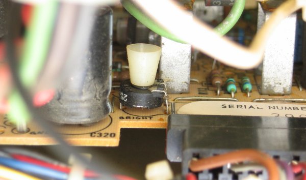
 The video problem was probably a contact problem, but not in the external controls. There is a six wire connector and cable from the VIDEO KEYBOARD INTERFACE to the monitor, not looking very solid, but that wasn't it. Disconnecting and reconnecting it (no power) or fiddling it (with power) usually has some effect. Neither the connector on the tube pins (lookout, unpleasant voltages here). An adjustment pot on the monitor board then? My board didn't look like either one in the Technical Reference Manual, but there was a small brightness pot in sight. At an awkward angle, so I exercised it a bit around its current position by hand (no power). This did the trick, the screen is now resonable stable.
While experimenting with the floppy issue, I removed the bar keeping the boards firmly in the mainboard. This bar is the only thing keeping them from falling out. I succeeded in switching the power on with an half inserted card. No screen data, not even sync, at maximum brightness the lines are visible, but do not cover the whole width of the screen. Probably a free running horizontal oscilator. So there was +12V. But the Power LED was off, which was an indication of a missing Vcc or +5V according the the Technical Reference Manual troubleshooting guide.
The power supply has a fuse for this, and my luck, this happened to be blown. Originally a 10A fuse, it happens to work too with 5A too (best match I had).
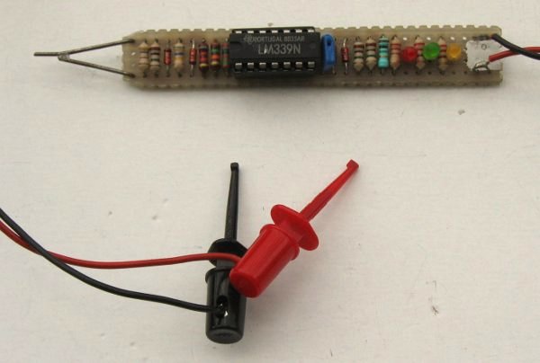
 Having deduced the floppy problem is in the signals to the floppy controller, I investigated those. A long time ago I made an improvised logic probe, with different LEDs for different logic voltage levels. Green for high, red for low and yellow for in between. My first suspect, "Disk Change" happened to be always low. This signal is connected to the PIO. It allows the Model II to actually wait for the floppy to be inserted before head load and reset to track 0.
 Looking for mechanical contact causes first, I checked the Service Manual for the floppy drive (Shugart SA800). There is a large "DOOR CLOSED SWITCH" (everything here is large), but not much wrong here. Very close is the board connection to the various peripherials, like the mentioned switch. Hmmm... Disconnect and connect again. Switch on Model II. It boots straight into TRSDOS. Always distrust old connectors, certainly card edge connectors. Gold plated or not, they can always fail.
Last update: 2021-08-05
fjkraan@electrickery.nl
 So I decided for a short switch on and see what would happen. I noticed one of the primary filter capacitors had already exploded and had leaked. The other capacitor, behind the coil looked ok, but was of the same brand so also suspect. Not only were both almost 30 years old, but dimensioned for 220V, while we have 230V nowadays.


