The original text was published on the Dutch TRS-80 site. This translation (and conversion to HTML) is by Fred Jan Kraan (2021-10-23). The original article can be found here.
Detailed modification instructions are in these two separate documents;
Recently we tested some small TFT monitors in the 5" to 9" range from sources like Alibaba and Aliexpress. In price these varies between 18 and 36 euro. The 5" display was readable (assuming good eyesight or proper glasses). At least better than the original Osbourne-1 display (5", 52x24 characters, introduced April 3rd, 1981 according to Wikipedia). TFT displays in the 7" to 9" are perfectly usable for the 64x16 character screen of the TRS-80 Model 1. Very useful for the Portable Model 1.
From the five monitors tested, only two could display the video of an unmodified Model 1. One 9" monitor had a fuzzy image, this one was discarded., The remaining two had images as shown below:
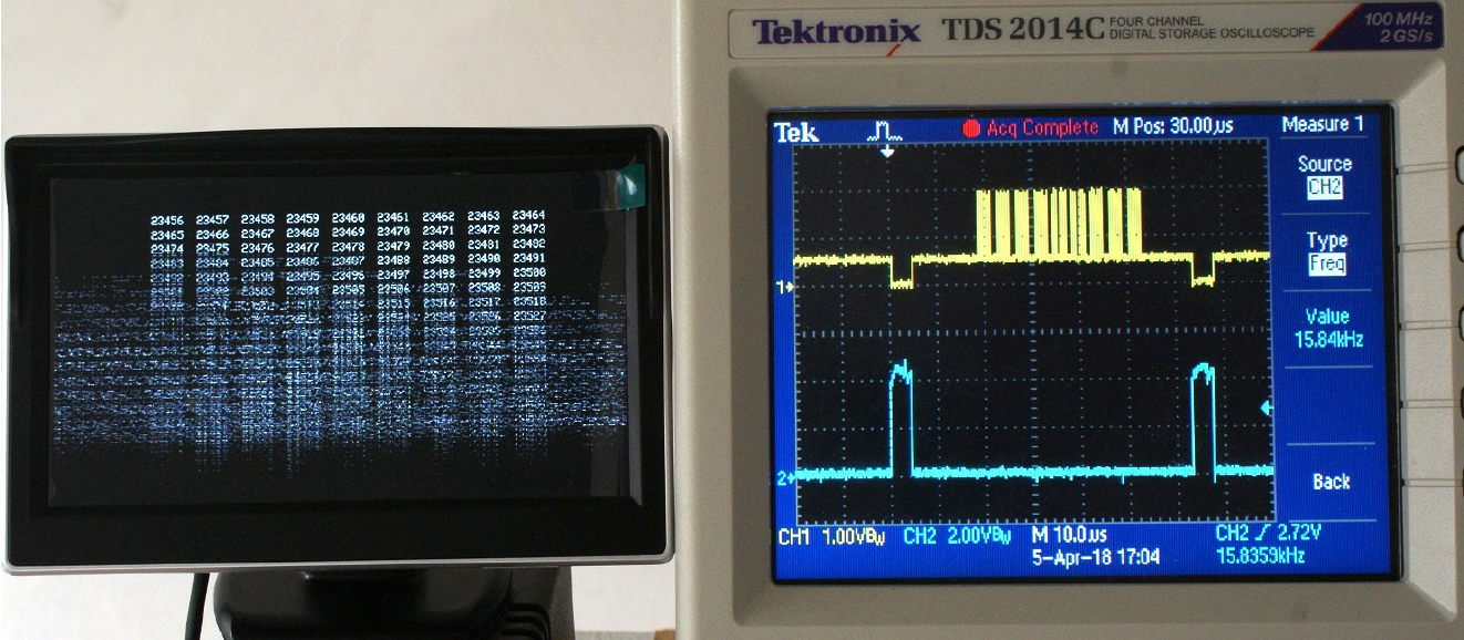
Image as shown on two small monitors (5" and 7") connected to a standard RTS-80 Model-1. The yellow signal on the oscilloscope is one video line (taken from video output), the nine vertical bars correspond with the nine 5-digit numbers on the row. In blue two line sync pulses (Z32-13, see schema). The line frequency is also displayed on the oscilloscope. It is 5 to 10 Hz too low.
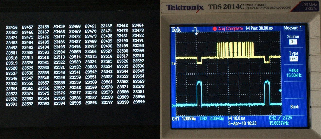
We were lucky to test the monitors with three Model-1's. One of these Model-1's gave a good image on all monitors. Below the result of this Model-1 with a line frequency of 15.6 kHz:
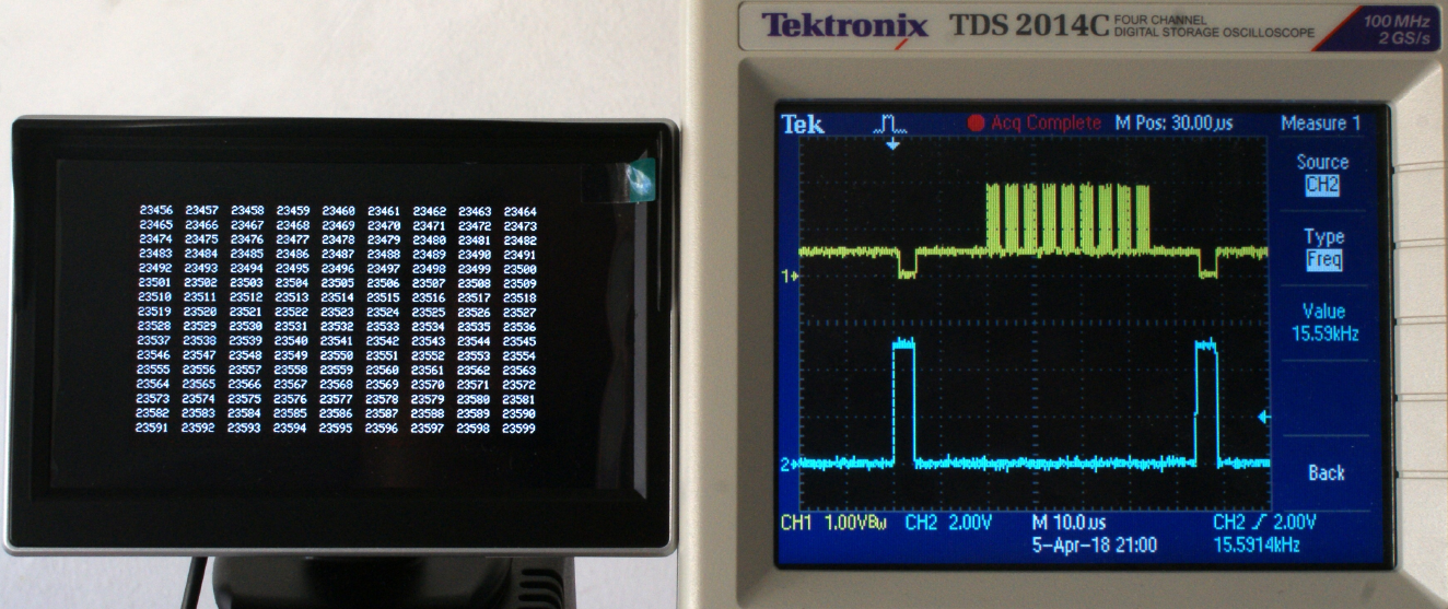
If one computer works properly and two don't, it is simple to track down the differences. The problem wasn't the video signal strength (2Vpp, while 1Vpp is standard). A reduced signal still had the problem. Further analysis learned us that on the working Model-1, the crystal was replaced.
The American Model-1 was created for the USA home market, where 60Hz field frequency is standard. Some calculations:
In regions with a different mains frequency (50 Hz) an annoying interference is visible whwn using an American TRS-80 Model 1. The Japanese Model-1 was switchable between 50 and 60 Hzwith four jumpers.
The conversion of a (USA) Model-1 starts with changing the row count from 22 to 26 rows per field. This results in a field frequency of 50.8 Hz, reducing the interference considerable. But even in the world of computer hobbyists, are purists who want an field frequency of exact 50 Hz. Only then the interference is eliminated completely.
Replace the crystal with a 10.4832 MHz crystal. Two examined Model-1's had such a crystal, one with text '10.483', another with '10.4832'. The calculations:
The ideal solution, satisfying every purist. Making the computer 1.5% slower is a small tradeoff. The solution in the Japanese Model-1 is more elegant. Here five lines were added with some extra gates, resulting in a close match with 50Hz, 49.97 Hz to be exact. This with the original crystal.
The video field of the original TRS-80 Model-1 computers with the original line frequency of 15.840 kHz was not properly displayed on two TFT-monitors. A Model-1 with the line frequency modified to 15.600 kHz did display correctly. The official PAL line frequency is 15.625 kHz, making the modified Model-1 a better match. The images above show that the first rows were properly displayed, the lower rows had increasing problems with synchronisation. This fits with our theory that line frequency mismatch causes the problem.
After some other experiments, the crystal in one Model-1 was replaced. This more or less proved the line frequency was the problem.
So the advice is to replace the crystal if the new TFT display doesn't want to work? The advice is sound, with one minor caveat: 10.4832 MHz crystals are hard to find nowadays. The same holds for the close matched 10.5 MHz crystals.
The other option is to change the line frequency divider chain. This divider factor is now 112, being the sum of 64, 32 and 16. The TRS-80 schema shows a triple-NAND gate (Japanese version) which resets the chain after counting each 112 characters (AND gate in American version). The alternative dividing factors are 113 (15.700 kHz line frequency) or 114 (15.562 kHz line frequency).
The solutions look good on paper, but factor 113 isn't close enough and factor 114 is not trivial. The IC that actual counts the character; 113th, (C1) or 114th, (C2) has to be reset too. For the 113th character just the 74LS93 for 'C1' can be reset, but for the 114th character, the 74LS93 'C2-C4' has to be reset. Problem is, this IC is also used to count rows (R1, A-Qa). Resetting this counter at 114 characters messes up the row counting. Another IC for the 2-divider A-Qa would solve the divide-by-114 counter-problem.
It appears, the only solution for a better matching PAL line frequency of around 15.625 kHz is adding another IC. The solution chosen is copied from Tandy's own way of adding rows. The same can be done by adding dots.
The calculations: 112 characters per line can also be expressed as (112*6=) 672 dots per line (10.644480 MHz divided by 672= 15.840 kHz).
By adding ten extra dots the line frequncy will be (10.644480 / 682 =) 15.608 kHz. This is comfortably close to the ideal of 15.625 kHz.
The IC added is a 74LS90, but for adding 10 dots, any other 10-divider could do, too. After counting 112 characters, when the character counter would be reset, the signal is withheld. The reset will occur when another ten dots are counted. During this time the dots-per-character counter also has to be stopped.
In other words; As soon as the character-per-line counter reaches 112, the 74LS11 (American Model-1) or the 74LS10 (Japanese Model-1) is activated.The 74LS92 dots-per-character counter is stopped and the extra 74LS90 starts counting dots until it reaches ten. After count ten, a chain of three events is started. The character-per-line counter is reset, the 74LS11 or 74LS10 is deactivated and the dots-per-character counter starts counting again for the next line.
To keep the schema simple, the extral 74LS90 is clocked by half the clock frequency, so it only has to count to five and the rising flank of counter value 6 can reset the character-per-line counter. So, the 'B'-input is connected to Clock/2, the 'A' input is connected to the 'D' output, and Qa is used to reset the characters-per-line counter.
This setup was tested with a 74LS92 (more of those were available). The test allowed variation in the number of added dots; 1, 2, 3,...9, 10, 12, 14, 16 and 20 extra dots were tried (adding four dots results in 15.750 kHz, used in NTSC). The solution worked as expected.
For a good image on the 5" monitor more than 7 dots had to be added. Below the result with just 7 added dots (10.644480 MHz / (672+7) dots = 15.677 kHz):
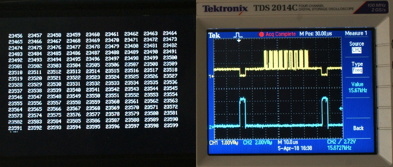
The lowest line should be black, but starts with four dots. So adding 7 dots just isn't enough. Note the 9 columns shown are circa 75 mm wide, the actual view is better than this photo.
No more than fourteen dots may be added (noting fifteen is not tested), The field with sixteen added dots (10.644480 MHz / (672+16) dots = 15.472 kHz):
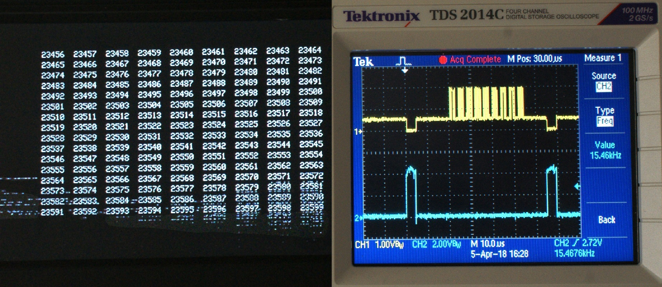
The low line frequency resulted in syncronisation problems in the lower four rows. In the intermediate range, i.e., between adding eight dots (15.654 kHz) and adding 14 dots (15.517 kHz) the field displays correctly. This is between PAL+29 Hz and PAL-108 Hz. PAL specifies 15.625 kHz as line frequency.
Adding 9 dots is the closest match to standard PAL, as it results in a line frequency of 15.631 kHz. The selection of ten dots makes the circuit added simpler and results in a line frequency of 15.608 kHz (= 10.644480 MHz / (672+10)):
Modifying the line frequency to 15.608 kHz will result in a field frequency of 50.02 Hz (= 15608 / 12 / 26), which is better than the 50.8 Hz field frequency before this line frequency modification was applied. So, this modification could also be used by those who want a better match with 50 Hz mains frequency. With this modification, for American Model-1's the match with 50Hz mains frequency is slightly better than the field frequency of a Japanese model-1 set to 50 Hz (50,02 Hz versus 49.97 Hz, respectively.
We did not / could not test our modification with NTSC compatible TFT-monitors. In addition, please note, in contrast to the original Model-1 monitor, TFT monitors are not subjected to interference with mains frequency, because they are powered by a DC power supply (usually 12 V).
The proposed modification is as close to 50 Hz as the official 50 Hz configuration. As described five extra lines are added during the blanking phase (see schema, three gates, one from Z44, Z45 and Z46). With the extra lines the total comes to (26 * 12 + 5 =) 317 lines. As the line frequency is 15.480 kHz, the field frequency in the Japanese Model-1 is (15480 / 317 =) 49.97 Hz.
When the line frequency modification to 15.608 kHz is applied to the Japanese Model-1, it is required to set Jumper-10 in the c(ommon)-1 position to keep the field frequency at 50 Hz. The correction with five extra lines (Jumper-10 in c-2 position) is then superfluous.
As a final remark, all four TFT-monitors had the specification 'NTSC/PAL compatible'. The tests above raises some doubts on this. Just two of the four were truely 'NTSC compatible'. NTSC requires syncing at 15.750 kHz. In practice one 5" monitor didn't; at NTSC + four dots (15.746 kHz line frequency), the field was as unreadable as with 15.840 kHz (standard TRS-80 Model-1 line frequency).
Truly 'NTSC compatible' monitors probably have no trouble with the TRS-80 line frequency, the difference is only (15.840 - 15.750 =) 90 Hz. It would explain the two working monitors.
April 7th, 2018