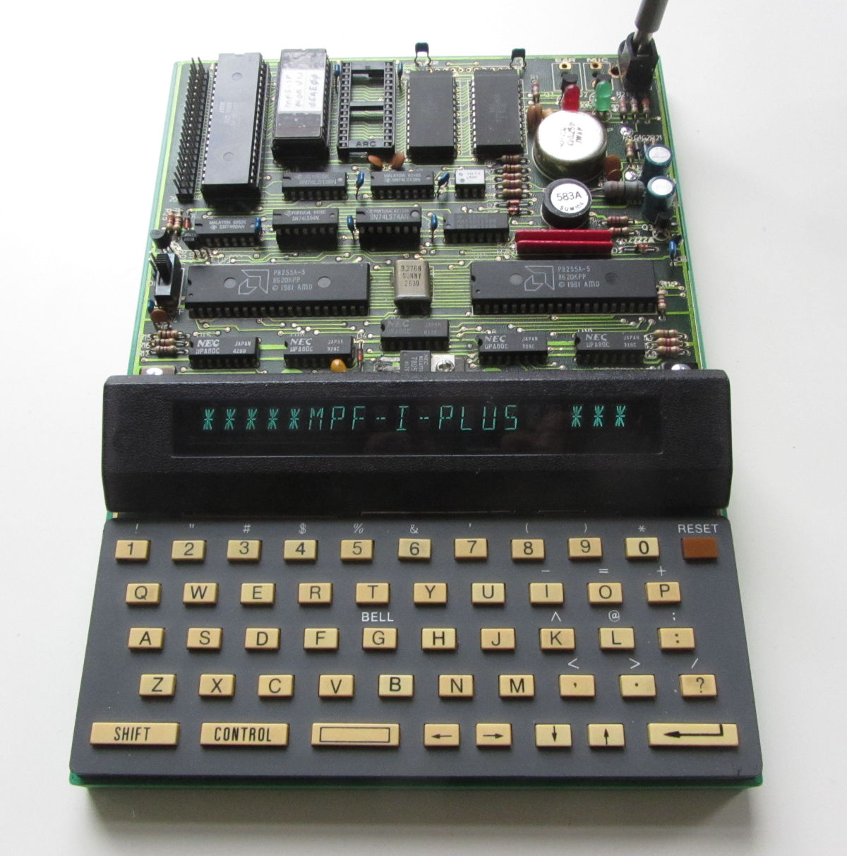
The computer came incomplete, but in overall good condition. The power connector, speaker and the monitor ROM were added. The cassette port sockets will come later.
Some minor repairs:
- The display brightness fluctuated with the number of digits in on-state, which was also reflected in the anode voltage. The standard -30 volt was reduced to about -18 volt with the startup banner on display. After making sure this wasn't caused by old, dried-out electrolytic capacitors (33uF/35V), the driver transistor, an old TO-18 2N2222A was replaced with a newer TO-92 of the same type.
- The crystal had an incorrect frequency: 3.27 Mhz, while it should be 3.58 MHz. Usually not a problem, but with the IOM-PRT-1P Baud rate derived from that, communication is 'confused'.
The MPF-IPlus supported a battery backupped RAM, assuming low-power CMOS RAM is installed. Below the board there is a holder for two AA-batteries and at the left a switch to enable/disable the battery power to the RAMs.
Some info about the VFD-transformer; it is a Sumida 583A and here are the resistance between the pins are (measured in circuit, no significant difference in polarity) and the voltage in operation:
1-2 : 0,32 ohm    6.4 Vrms
3-4 : 0,34 ohm    1.0 Vrms
5-6 : 0,86 ohm    3.5 Vrms
6-7 : 0,91 ohm    3.5 Vrms
8-9 : 11,0 ohm     40 Vrms
The usage of Vrms might be dubious for square wave signals like this, some were quite spiky. The frequency is 200 kHz +/- 20 kHz. The values might be a indication of winding ratio's. |
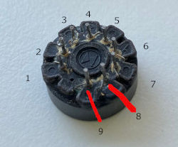 Photo by Bart Sattler |
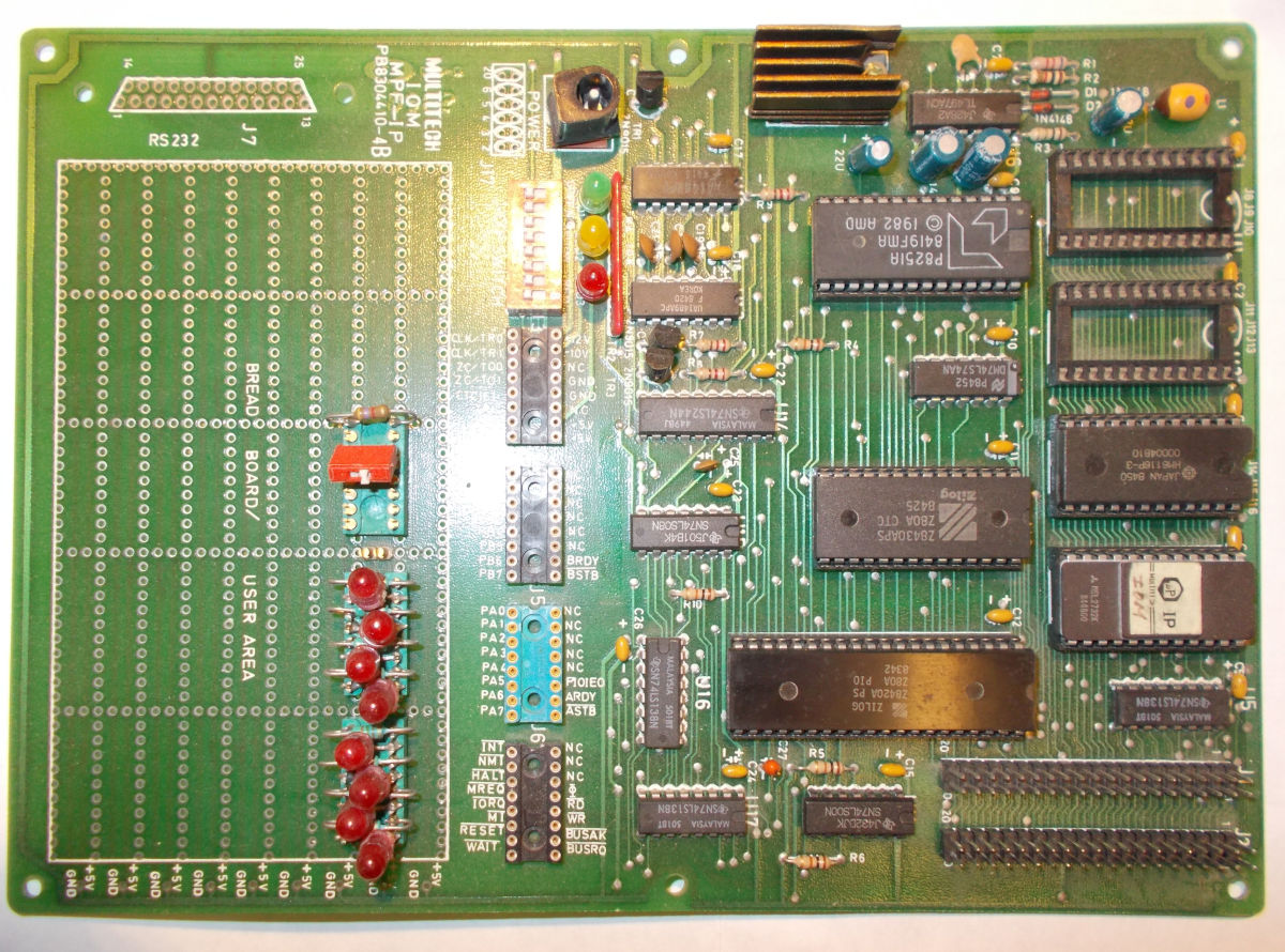
The contents of the ROM is a bit underwhelming, as it are mere simple demo's for the interface chips:
- B000h
- PIO demonstration using the three LEDs as traffic light.
- B100h & B700h
- CTC demonstration as a clock. Two versions.
- B300h
- PCI & CTC demonstration of reading the DIP-switches for the baud-rate, and sending a message over the RS232c interface. If a CRT (TVB-MPF-1P) board is present in the configuration, a message is send there too.
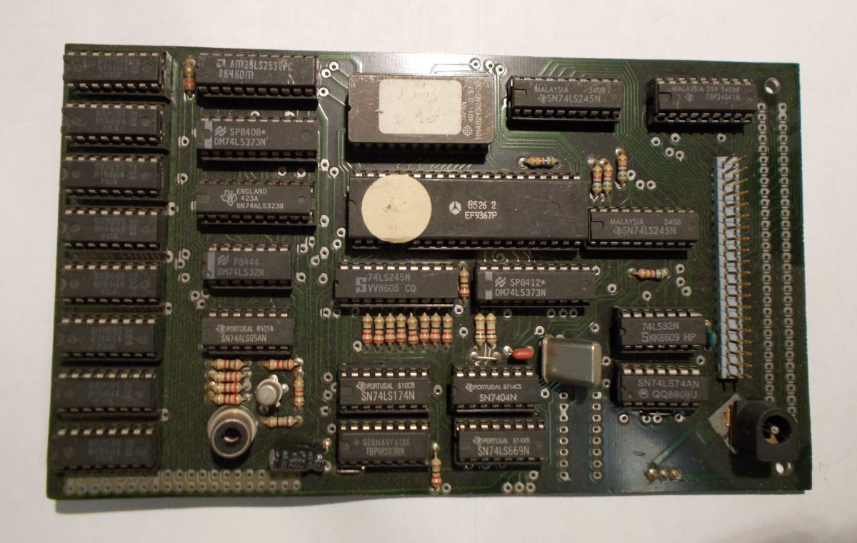
************  IOM_MPF_IP  ************
     FEB. 13TH 1983 by Charles Chang
  IOM_MPF_IP is an I/O memory board.
The address of ROM is from B000H to BFFFH.
The address of RAM is from D800H to EFFFH.
The I/O address of DIP-switches is from 6CH to 6FH.
The I/O address of PIO is from 68H to 6BH.
The I/O address of CTC is from 64H to 67H.
The I/O address of 8251 is from 60H to 63H.
It contains three demo. programs.
The first program uses PIO as a traffic light controller.
The second program uses CTC to design a clock.
The third program transfers data between IOM_MPF_IP and CRT through RS_232.
There is a remake of the IOM-MPF-1P, but it was never finished.
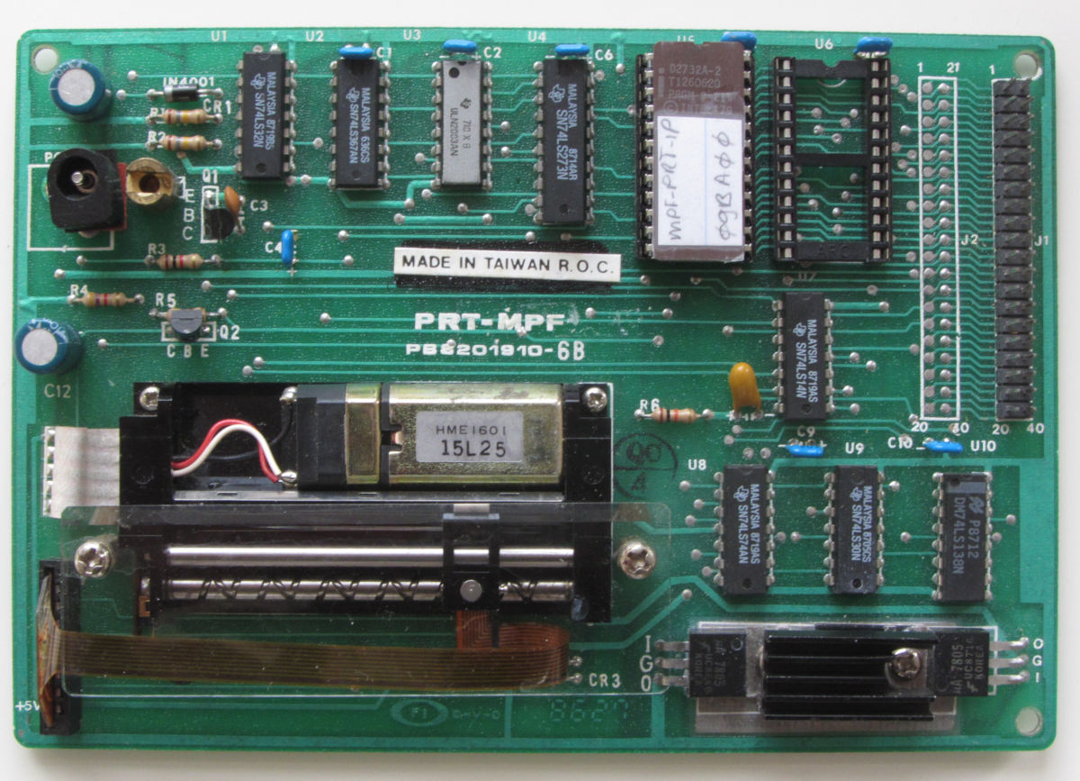
The printer is a Daini Seikosha MTP201A thermal printer, capable of 20 characters per line or 138 dots. The driver uses characters of 5x7 dots. Paper width is 58 mm, of which 46 mm is used for printing.
The PRT-MPF-IP ROM contains four routines:
- SHIFT (6A00h) Drive the thermal head shift right
- PLINEFD (6A10h) Line Feed
- PLINE (6A30h) Drive the paper vertically by two lines
- MTPPRT (6A40h) Print out the contents of line buffer (used by MPF-1P monitor)
The MPF-1P monitor checks for the presence of a PRT-MPF-1P during startup by reading address 6000h (start of the PRT-MPF-1P ROM). If the value is CDh, a printer is assumed to be attached. Ctrl-P toggles the display output to the printer. The displays then reflects the printer state: 'PRT ON' or 'PRT OFF'
While printing, the printer draws considerable current, more than 1.5A. Make sure you use an appropriate power supply.
There are several versions of the board, which is usable for both the MPF-IP and the MPF-1(B), but with different ROMs. The second ROM socket is mapped to the 7xxxh region.
The ROM location is probably 0xA000 - 0xA7FF, The EF9367 registers are accessed in 0xAFE0 - 0xAFEF range (this is derived from a ROM-disassembly).
Image is from
forum.system-cfg.com.
The board appears to support two busses, the MPF-I bus (just the CPU
pinout, minus +5V) and possible the
ECB-BUS.
The boards looks like it is a third party design.
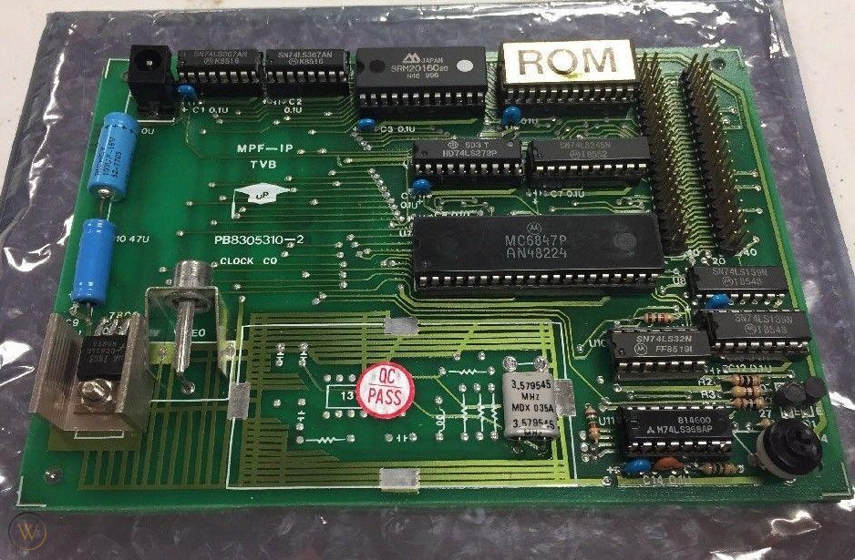
Image is from forum.system-cfg.com.
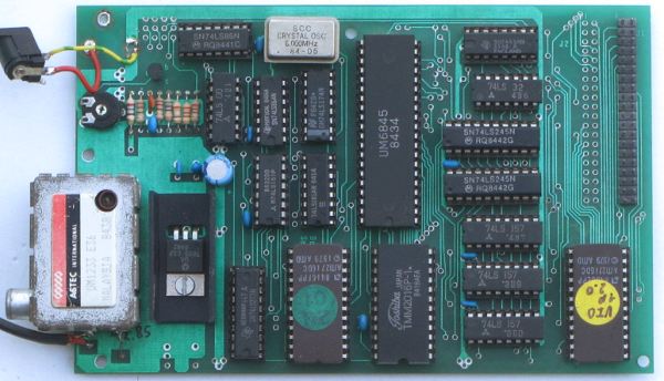
This uses an MC6845 CRT controller and generates a 40 x 20 video signal, that isn't quite PAL compatible. Not a problem for the old vacuum tube analog monitors, but modern TFT-displays want something more standard.
There are at least two versions of this board; the original with the EPROM at 0800h-0FFFh and RAM at 3000h-37FFh, and a newer version with EPROM at A000h-A7FFh and RAM at 4000h-47FFh. For the original version the monitor ROM on the MPF-1 was exchanged by a combined monitor (0000-07FFh) / VIDMON ROM (0800-0FFFh). But the later MPF-1B had a monitor / Tiny-Basic ROM. So the VIDMON ROM was relocated to A000h-A7FFh.
Useful routines for version 2.0:
- A001h - Initialisation of the 6845 and integration into the monitor.
- A004h - init 6845, clear screen, return from call
- A007h - init 6845, clear screen, jump to 0000h
- A00Ah - (JCRTCO) print character in C, interpret control codes
- A00Dh - (JCRTOU) print character in C, print codes 00h-31h too
- A010h - (JTEXCO) print 00h terminated string (start in IY)
- A013h - (JTEX??) print 00h terminated string (start in IY) CR = LF
- A016h - writes character set to screen
- A019h - configure 6845 with register/data table in HL (FFh terminated)
The 2.1 and 2.2 versions were developed for the MPF-1(B), and might not work on the MPF-IP.
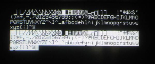
The character set image is the result of the key sequence: [ADDR], A, 0, 0, 7, [GO], [ADDR], A, 0, 1, 6, [GO].
The 2.0 ROM has a deliberate routine to replace every printed [`afg by afhi^. Why is a mystery to me.
The manual for version 1.0 is at the Virtual library. A modified ROM is also available here fixing the character mangling.
One way to use it is to copy the data from the ROM in the range a49dh-a4c1h to RAM, modify the even values, load the start address in HL and jump to A019h.
Annotating the disassembly and adding features is a work in progress at: github.
There is now a remake of the VIO-MPF-I!
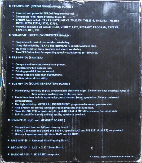
- SGB-MPF-IP - (Sound Generator Board)
- Manual play: One easy-to-play programmable electronic organ. Twenty-one-keys covering a range of three octaves, enabling you to play any tune.
- Useful functions include Auto replay, Auto rhythm, Sound synthesizer, Melody and sound demonstration.
- Use high reliability GENERAL INSTRUMENTS programmable sound generator chip.
- 4kB EPROM for storing sound generation programs and sound data.
- Share the Z80 CPU as host controller and 4k RAM of MPF-IP as memory for sound data.
- Build-in amplifier circuit and high quality speaker is provided.
- UWB-MPF-IP: Universal Wire-Wrapping Board
- BBD-MPF-IP: 1.42" x 3.15" Bread Board.
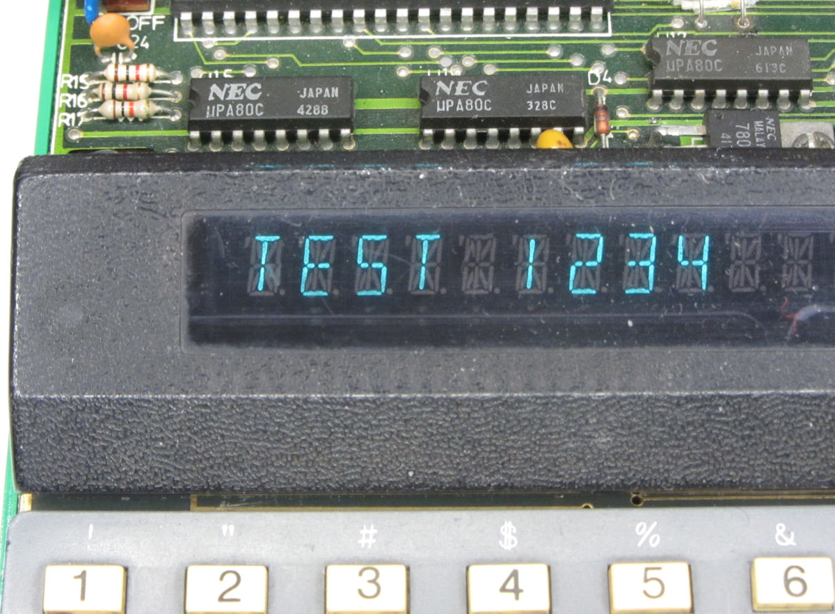
This is the code to get a single string on the display. Other calls allow for composing a string in the input buffer and convert the whole buffer to 14-segment patterns for the display.
Z80-Assembler	Release 1.9	Wed Jan 11 10:41:20 2023	Page 1
Source file: test_1234.asm
Title:

LOC   OBJECT CODE   LINE   STMT SOURCE CODE
                       1      1
00e6                   2      2 ESCAPE: EQU     000E6h ; Re-enter monitor
09b9                   3      3 CLEAR:  EQU     009B9H ; Clear DISPBF, reset DISP and OUTPTR.
0886                   4      4 PRTMES: EQU     00886h ; Call MSG. If a PRT-MPF is connected,
                                                          output to printer too.
0246                   5      5 SCAN:   EQU     00246H ; Call SCAN2 and BEEP.
                       6      6
                       7      7         ORG     0F900h ;
                       8      8 START:
f900  cd b9 09         9      9         CALL    CLEAR  ; Clear display.
f903  21 0f f9        10     10         LD      HL, MYMSG ; Point to start of message text.
f906  cd 86 08        11     11         CALL    PRTMES ; Calls MSG, calls DEC_SP,
                                                          sets IX to DSPBF
f909  cd 46 02        12     12         CALL    SCAN   ; Display the buffer contents and
                                                          wait until a key is pressed.
f90c  c3 e6 00        13     13         JP      ESCAPE ; Back to monitor.
                      14     14
f90f  54 45 53 54     15     15 MYMSG:  DEFM    'TEST 1234'
f913  20 31 32 33     15     16
f917  34              15     17
f918  0d              16     18         DEFB    0Dh
f919                  17     19         END