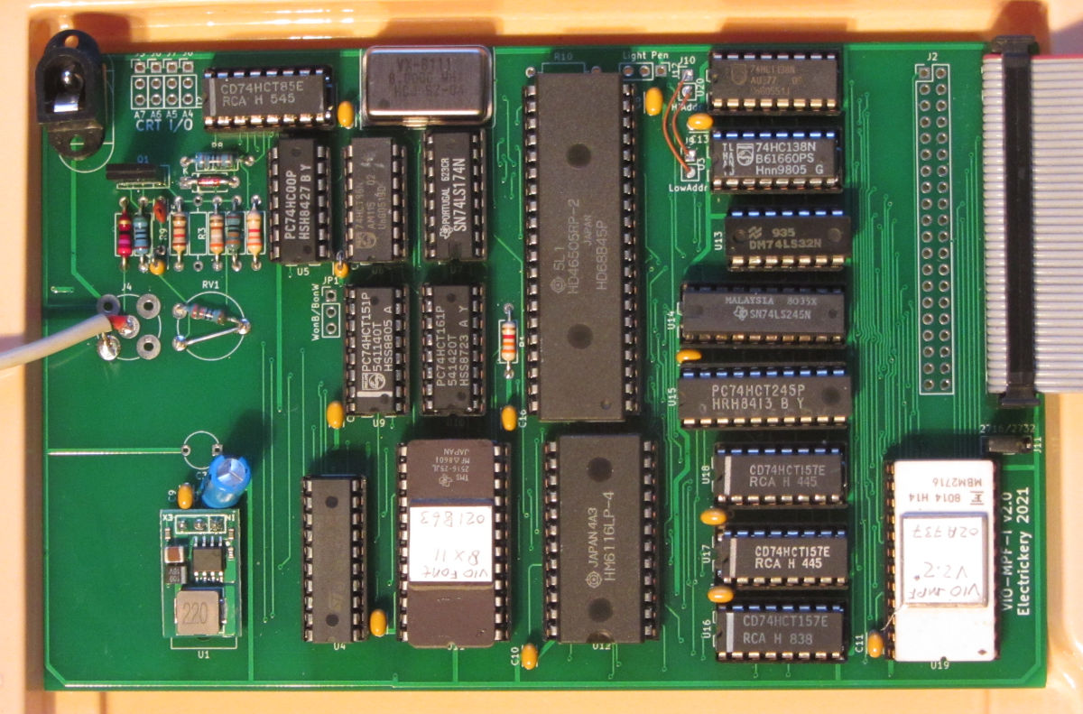
The VID-MPF-I v2.0 is an updated remake of the Bardehle Electronic Video-MPF-1 v1.2 board. Some components are replaced by more common logic, and the ROM is cleaned of what appeared as debug code and experimental features. Additional routines, useful for testing were added. The current footprint is less than 2 k Byte. The socket is designed to take a 4 k Byte ROM too, so plenty room for more features.
Bardehle produced at least two versions of the board and software.
The first remake is marked 2.0. During component assembly and testing some problems were found. The problems were:
The versions 2.1 and 2.2 of the monitor firmware are made for the MPF-1(B), but the MPF-IP works best with the 2.0 version. The 2.0mod version eliminates the mangling of some ASCII characters, the 2.0modpal version adheres better to the PAL-video standard, making it work better with modern flatscreen monitors.
There were two sources for the remake: a board version 1.2 and the schema in the manual for version 1.0.
List of changes:
The original 1.0 firmware contained little more than routines for initialisation and print characters and lines of characters. It also recognized eight control characters. The version found on the 1.2 card added a character set dump and some badly understood (based on dis-assembly) additions.
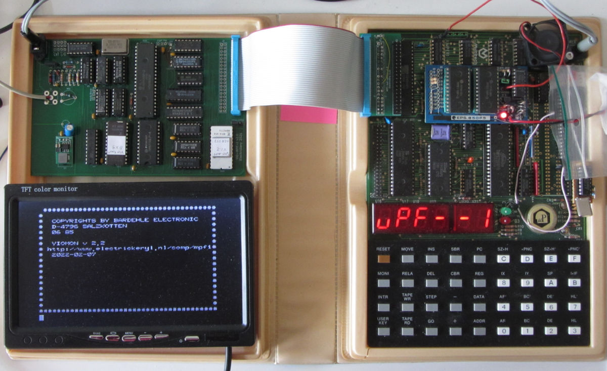
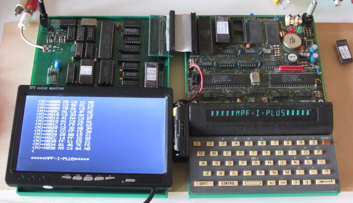
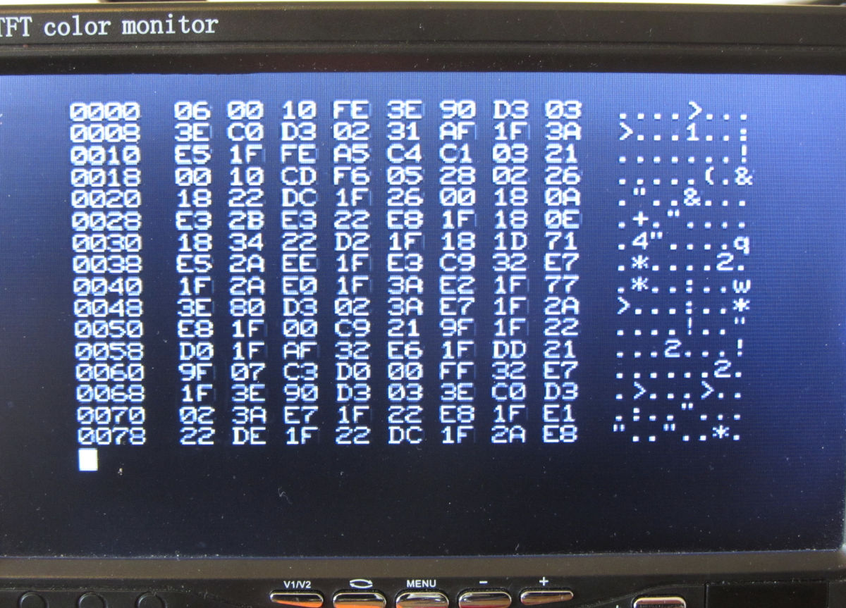
To properly test the remake, at least some routines had to be added. Currently a screen-filling banner with copyrights is present as well as a simple hex-ascii memory dump. The former is useful to make sure the whole display-memory is visible on the physical display. The latter adds an option to look at more than one byte in memory at once.
The github page is the proper place for an up to date list of features, but here a short list:
    0a000h: clear screen, reset cursor
    0a004h: init 6845, clear screen, return from call
    0a007h: init 6845, clear screen, jump to 0000h
    0a00ah: (JCRTCO) print character in C, interpret control codes
    0a00dh: (JCRTOU) print character in C, print codes 00h-31h too
    0a010h: (JTEXCO) print 00h terminated string (start in IY)
    0a013h: (JTEXCLN) print 00h terminated string (start in IY) with line
     end (CR/LF) post-fixed
    0a016h: (JVIDTE) writes character set to screen, jump to 0000h
    0a019h: init 6845, clear screen, print banner, rst 0
    0a01Fh: hex/ascii memory dump of 8 * 16 bytes, rst 0
In the housekeeping section of the video-RAM, some addresses are
of interest:
The code is default assembled at A000h, but intended to be relocatable (assembly-time). Most development and testing is done with the ROM-emulator from the U7 socket at 2000h.
The original code contains provisions to write only to video memory during the blanking period, but not all variants of the 6845 have the register indicating this. The 6545 has it, as does the UM6845, but the HD6845 doesn't. Video memory is what could be visible, but also video- housekeeping. It still works, but with black stripes in the video signal.
The range from 4000h to 45FFh is used for the actual display. At one time, only 40x20 bytes (=800 bytes, 320h) are visible, but as lines are printed, the displayed part scrolls through the reserved space of 1536 (=600h) bytes. The house-keeping part (4600h-4660h) is used by the firmware for house-keeping (cursor position, line buffer, ...). The rest is free to use. But using it can result in striping in the video signal.
Last updated: 2025-09-27