RWC-AI
These racks are the property of Jaak Bartok, who allowed me to borrow and describe them. Thanks, Jaak!
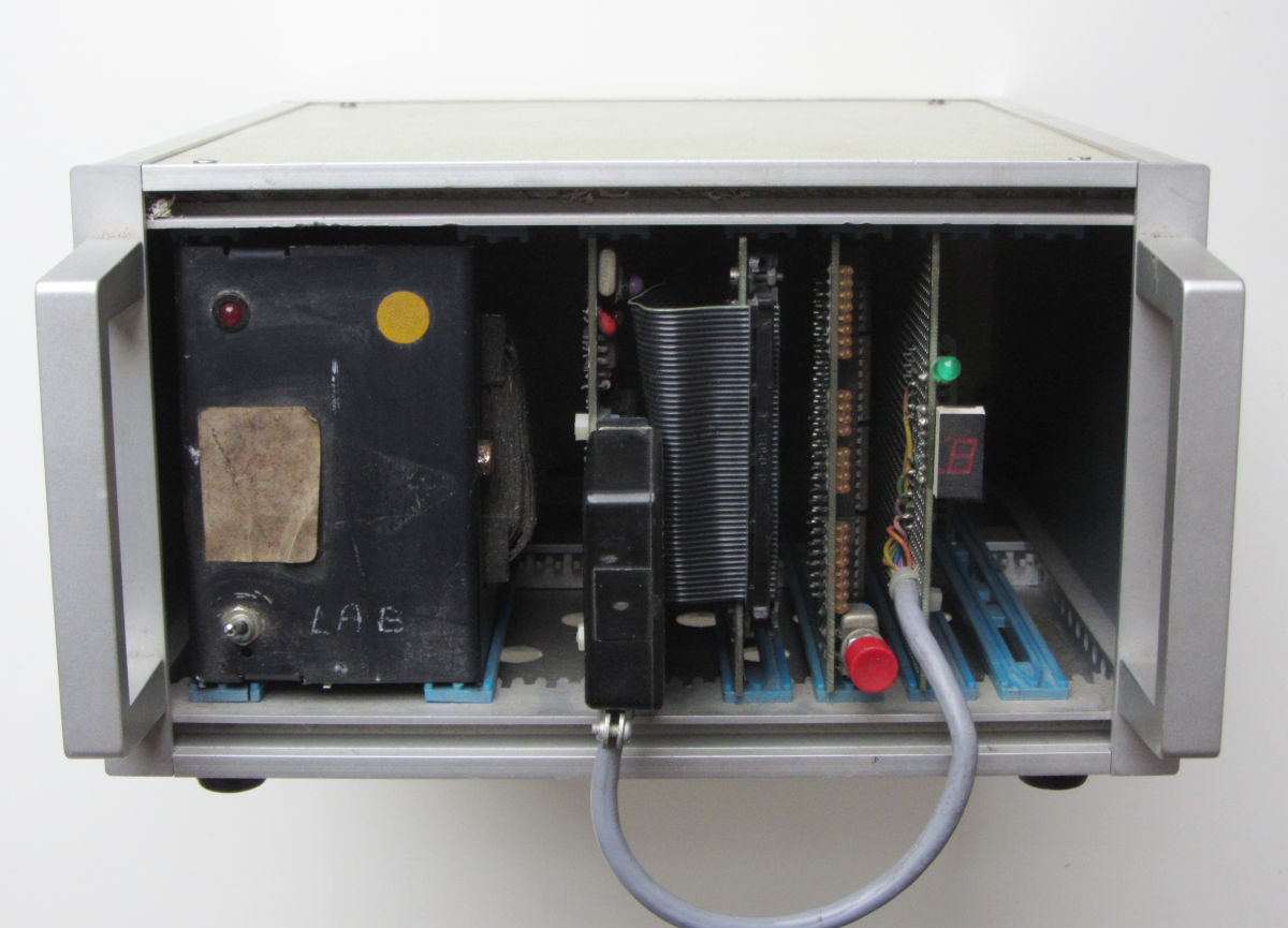
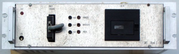
An interesting application of both the DAI computer and RWE cards is this rack. It contains one RWE card, an A/D converter and a DCR mini tape drive. The DAI computer in this installation had a special video interface
allowing a video camera image to be superimposed on the screen. A camera could be moved in two dimensions
and an angle. The positions were converted to 0-20mA signals, allowing the DAI to print the current
location and direction of the camera next to the camera image.
The installation was used in the Doel I + II nuclear power plant in Doel, Belgium.
This rack is a development system, originating from DAI/Indata itself. The current ROM contents seems to be a firmware for the Transimate, which seems to be a kind of CNC.
| Development rack | 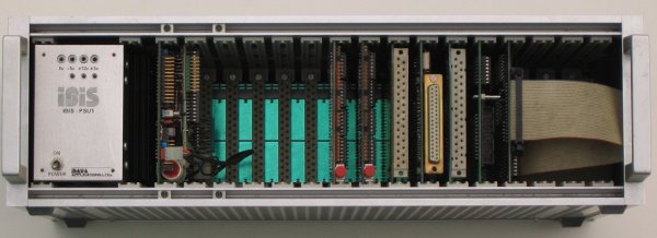 |
The rack contains an Z80 card, two monitor cards, two extender cards, a digital I/O card, a FIFO card and a disk controller card. The power supply is from a third party, Ibis, but apparantly custom made for DAI. |
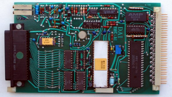
| SEC-Z80 card | 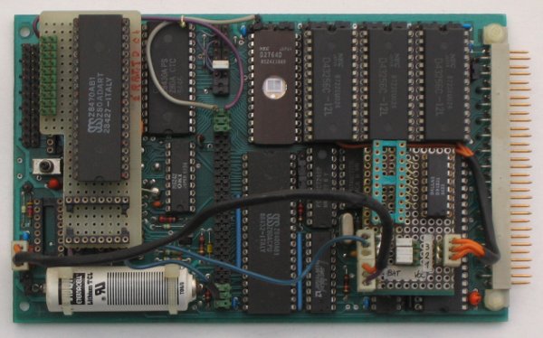
|
This card contains a Z80 cpu, Z80 DART, Z80 CTC, RTC (OKI 6242), 8 kByte ROM, 96 kByte RAM and a 8255 for the bus. Modifications are a custom RS-232 level converter, bypassing the 1488/1489 sockets, and battery backup for the RAM. The current firmware has a console on channel A of the DART. (9600Bd, 8 bits, no parity, 1 stopbit). More info with the custom card for the project. |
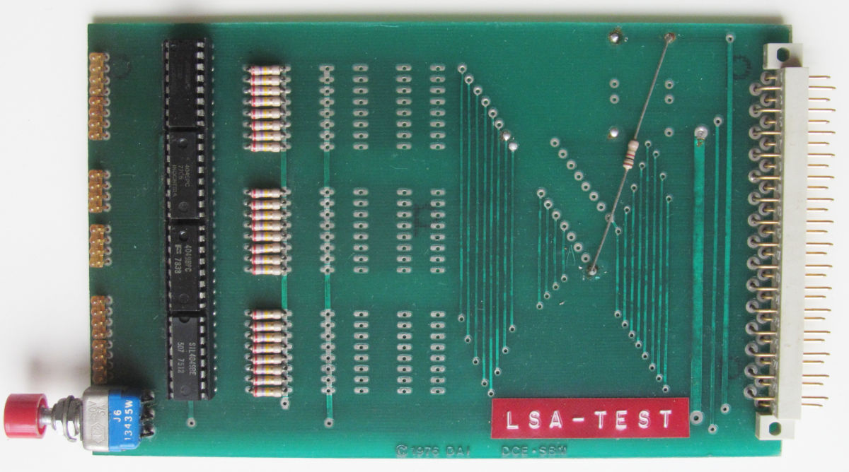
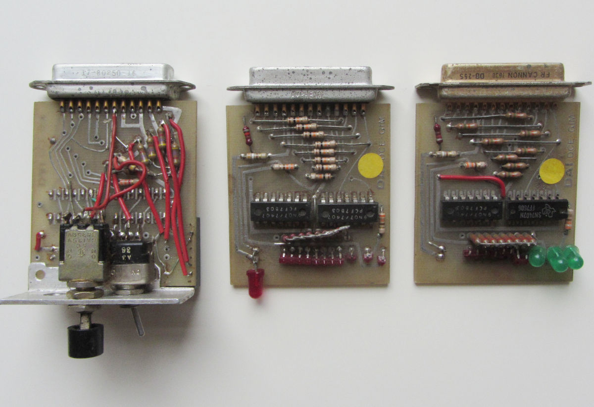
| DCE-SBM card | 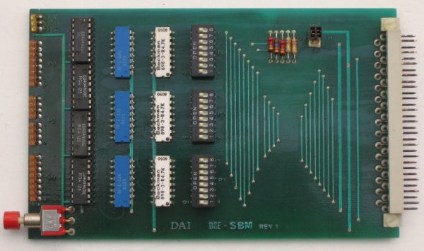
|
These cards contained dip-switches to emulate inputs and leds to emulate outputs. Apparently only useful for direct bus usage, not in RWC card mode.
|
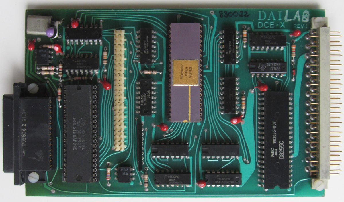
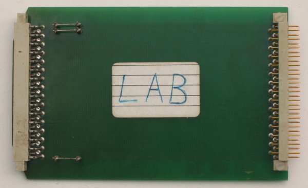
| DCE-EX card |
|
Not very exiting, but useful in combination with the monitor cards, for easy access to the dip-switches. |
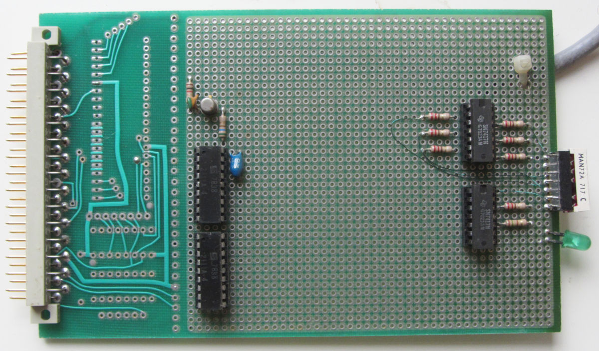
| RWC-T24 card | 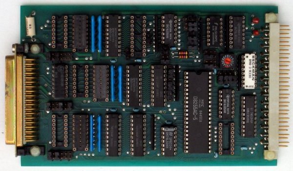
|
This is the "Generic TTL interface module". Quite a lot of interfacing for 24 digital lines. |
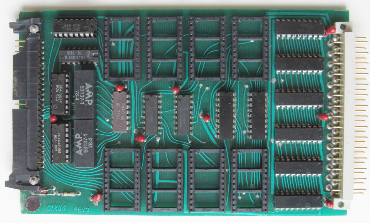
| RWC-F/F & FIFO 501 |
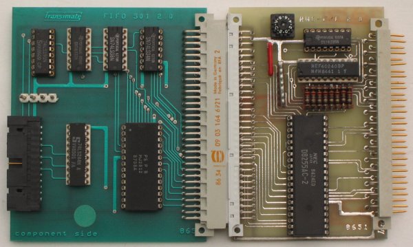
|
A card contraption based on a 32 byte FIFO. Both parts have the logo "Transimate", at one time a
trademark of Fabricom S.A., which is now part
of the GFD Suez Group. Fabricom, or FSA as it is now known, is
specialized in assembly systems.
Prompt: "next command" All commands are executed directly. They are: 0 - prints "checksum error" 1 - prints "checksum error" C - prints "TRANSIMATE RUNNING", and dumps binary? data R - prints "TRANSIMATE RUNNING", and dumps binary? data S - prints "checksum error" T - prints "checksum error" |
| Indata disk controller |
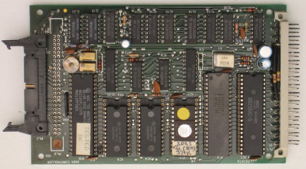
|
This floppy disk controller is quite an update from the original PDM-FDC card. This is an 8085 based card with a WD2797 FDC. The only board explicitly labeled Indata, the company that took over after the DAI bankrupcy. |
This rack is a development system, originating from DAI/Indata itself. There is no firmware in this rack.
Updated: 2025-10-17