DCE-1
DCE-KDU
DCE-EXPERIMENTER
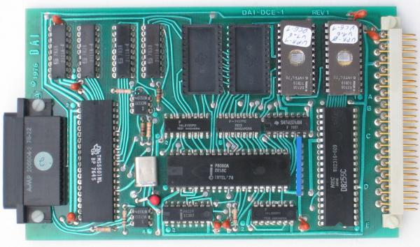
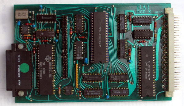
| Processor card DCE-1 |
|
This card is a predecessor of the DCE-X displayed below. The card contains both RAM (4 * 2111 = 512 bytes) and ROM (2 * 2708 = 2 kByte, extendable to 4 * 2708), so was a single board computer. A 8255 for the RWC bus and a TMS5501 controlling the KDU via the 25 pin connector. The ROMS contain the monitor program using the KDU as user I/O. The 8255 is memory mapped at addresses 1C00-1C03. The 5501 is memory mapped at 9800-980F. This chip implements an interesting interrupt mechanism for the 8080. The chip contains five timers, I/O pins and a serial port and generates eight different interrupts. When the 8080 acknowledges the interrupt with the INTA signal, the 5501 provides the RST instruction. The Connector layout. |
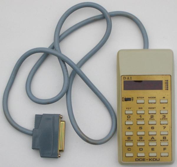
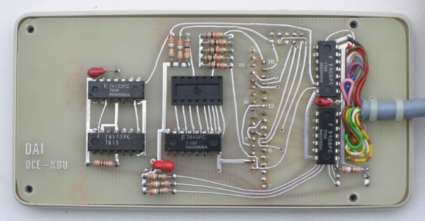
| Keyboard/Display Unit DCE-KDU |
|
This calculator like device allows the user to interact with the monitor program. Both work, but any documentation is lacking, so operation has to be reverse engineered. The KDU contains only simple logic, so keyboard/display scanning is done in the monitor. Image of the inside. |
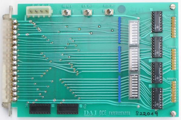
| Experimenter card DCE-EXPERIMENTER |
|
This board allows experimenting with the DCE bus. Drivers and LEDs for outputs, pullup resistors and dipswitches for inputs. A power connector (-5,+12,GND,+5V) and some reset and interrupt controls at the top. The sockets at the bottom are test points for each line. At the left the connector to the DCE-1. The Connector layout. |
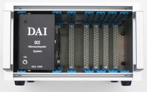
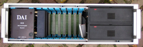
| Rack 9.5" | |
Room for four I/O cards. |
Property of Jaak Bartok
List of cards:
In the scanned document section is a copy of the DCE MICROCOMPUTER SYSTEM DESIGNER'S HANDBOOK describing the architecture of the RWC cards.
Updated: 2025-09-05

