LNW80 Microcomputer Operations Manual

SECTION 6: POWER ON

Connecting AC Power

   As  you prepare to hook up to the main power supply, ensure
that the computer and all peripherals are switched OFF.

   Locate the power cord exiting from the rear of the computer
and plug it inta a 110V AC outlet. All peripherals attached to
the   computer   must   also   be   supplied   with  AC  power
independently.

Turn   on   the   monitor  and  let it warm up for a minute or
two,

Power Up & Reset for Non-Disk Owners

   Press the BREAK key and switch the  computer  on.  After  a
moment's  hesitation,  the  computer  will  respond  with  the
following prompt:

                      MEMORY SIZE?
                      MEMORY SIZE? _

   (If  this is not displayed clearly or if the monitor is not
in a cooperative mood, see the relevant sub-sections below  on
monitor adjustment).

   We may ignore the MEMORY SIZE? question for the moment (see
SECTION 10) and simply press the ENTER key.

The computer in its turn replies with,

READY
>_

   To  restart  the  system in ROM once the power is on, press
the  BREAK  key  first   and   then   the   two   RESET   keys
simultaneously.

Power Up and Reset for Disk Owners

     - Switch on drive(s).

     - Switch on computer.

     - Wait until drives stop running.

     - Insert the system disk in drive 0, with the label
       facing the arm of the door (see Figure 6.0).

     - Close the drive door gently. The door will not
       close if the disk is not fully inserted.


     - Press both RESET keys simultaneously. The computer
       responds with the system logo.

Figure 6.0 You should now make a backup copy of your system disk before proceeding any further. This is most important. It is not beyond the realms of possibility to destroy the information on disk at this initial phase of investigation and experimentation. The BACKUP utility is described on page 80 of the DOSPLUS manual. Disk Power Up Malfunctions If the drives fail to stop running after switching the computer on or the system fails to boot, check the following: - Are the drive cables connected correctly and securely at both the computer and drive outlets? Note that the drive connection is "backwards" relative to TRS80 Model I, with cable up vs. down. - Is the disk in drive 0 a system disk? - Is the drive running smoothly? If not, the disk is not securely mounted on the drive spindle. Re-insert the disk. To RESET the disk operating system (to "boot" the system), hit the two RESET keys simultaneously. Monochrome Monitor Adjustment 1. BRIGHTNESS - turn fully clockwise. 2. CONTRAST - turn fully clockwise. If the display is not stable (ie. rolls vertically, horizontally or tears diagonally) make the following two adjustments. If the display is stable, then skip this section and go on to final adjustments. 3. HORIZONTAL HOLD - adjust for a picture that does not "tear" diagonally and is stable horizontally. It may still have vertical roll at this point. 4. VERTICAL HOLD - adjust for a picture that does not roll vertically and does not have any multiple or overlayed images. Make the following final adjustments: 5. BRIGHTNESS - turn counterclockwise till the background scan lines are just no longer visible (but the letters should still be brightly displayed. 6. CONTRAST - turn counterclockwise for the sharpest, roundest characters with a bright, easy-to-read display. The individual dots that make the letters should be visible, and the black space between the letters Z and E at the top and bottom of the letters should be seen. The following drawing illustrates this: Figure 6.1 - High and normal contrast drawings

GOOD CONTRAST CONTRAST TOO HIGH If you cannot achieve crisp characters with the following adjustments, then either - adjust the SIGNAL ADJUSTMENT (if any) to reduce the amplitude of the video OR install a series resistor in line (10 - 33 ohm) with the "hot side" of the video cable. If you intend to use the LNW80 computer in the inverse video display mode, then you will have to repeat the above adjustments while in the inverse display mode. Most monitors will probably not be properly adjusted for both inverse and normal display modes with the same settings. When you turn on the inverse display mode, don't, be suprised to see the screen go blank. When adjusting for BOTH display modes simply adjust to your own preference. NTSC Color Monitor Adjustment An NTSC color monitor has some of the same adjustments as your home television: BRIGHTNESS (may be called BACKGROUND), CONTRAST, COLOR, TINT, VERTICAL H0LD, HORIZONTAL HOLD and SHARPNESS (sometimes called FOCUS). The first step of alignment is to perform the same adjustments, as with a monochrome monitor (the procedure is listed in the previous section). Some of the controls found in a monochrome monitor (i.e., horizontal and vertical sync) may, or may not be present in your color monitor. If the control cannot be found, then it should be assumed that the control is automatically set internally and needs no adjustment. Check the owner's manual for more details concerning your monitor. Monochrome Operation The NTSC color monitor cannot display the 64-column text screen with clarity. With some monitors it may be possible to read the characters in this mode, but it will require the optimum setting of the above-mentioned controls and a very high quality set with a +6MHz luminance bandwidth. It may also require that the NTSC color monitor be connected to the B/W video output since the bandwidth is higher through that display channel, and the color setting on the set should be turned completely off. Color Operation In order to align your monitor for color operation, you must first display the color bar pattern generated by the program listed below. IF THE NTSC MONITOR IS YOUR ONLY MONITOR, THEN YOU MUST PERFORM THE MONOCHROME DISPLAY ADJUSTMENTS MENTIONED IN THE PREVIOUS SECTION TO MAKE THE DISPLAY READABLE WHILE TYPING IN THE PROGRAM THAT IS LISTED BELOW. This program is written using LNWBASIC and is easy to type in. It does require that the programmer has a working knowledge of DOSPLUS 3.4 and LNWBASIC. These details can be found elsewhere in this manual and in the LNWBASIC USER MANUAL or the DOSPLUS 3.4 USER MANUAL. 1 'LNWBASIC Color Bar Test Program 10 MODE2 20 PCLS 30 FLS(191) 40 FOR X=0 TO 7 50 COLORX 60 Xi=16*X:Y1=0:X2=(16*X+14):Y2=191 70 LINE Xl,YlgX2,Y2,SET,BF 80 NEXTX 90 END Once you have typed in the program, save it for future use by typing: SAVE"COLOR/BAS" This program should generate 8 color bars in the following order: White Green Yellow Red Magenta Blue Blue-green Black. Once the color bar program has been run, make the following adjustments: 1. BRIGHTNESS (May be Called BACKGROUND) - adjust such that 7 color bars (may appear as 7 grey areas) appear, but the BLACK bar (eighth bar) at the right of the screen is completely black. 2. CONTRAST - adjust so that the bars have adequate range of intensity. The BLACK bar should be black, and the WHITE bar should be a bright white. The thin black borders between the color bars should have the sharpest edges attainable. 3. COLOR - adjust so that the colors (may not be the correct colors yet) are bright and clean, but not saturated so much that there is color "bleeding" and distortion in the black borders between the color bars. 4. TINT - adjust the tint so that the colors displayed on the screen match the 8 color bars and suit your individual preference. From left to right: white green yellow red magenta blue blue-green black 5. SHARPNESS - Between the color bars are thin, two-pixel borders of black. Adjust the sharpness or focus such that the sharpest edges are obtained. RGB Monitor Adjustment and Operation The RGB monitor generally requires no more adjustments than a monochrome monitor: l. Perform the MONOCHROME MONITOR ADJUSTMENTS 2. Type in the COLOR BAR program listed in the previous section and run it using LNWBASIC. Power Off When turning off your computer, allow at least 15 seconds before turning it on again. This time allows any power that may not have drained away in the electrical circuitry to do so, Memory Test Although your LNW80 has been thoroughly tested at our manufacturing plant, we include this memory test in case you ever need to use it in the years ahead. 10 REM Memory Test for LNW80 20 REM This is a simple test of computer memory. 30 REM Each memory location is tested by using the 40 REM the GOSUB instruction. It should run 50 REM continously until it reaches location 100 60 REM or so. Total memory is printed on the top 65 REM left hand corner of the screen. 70 CLS 80 PRINT CHR$(23) 85 PRINT @ 0,MEM 90 PRINT @ 470,MEM 100 IF MEM < 100 THEN STOP ELSE GOSUB 90 Now type: RUN means that you press the ENTER key after typing RUN. The program should run continuously until location 100 or so is encountered. High Speed / Low Speed Test We can make convenient use of this program to do another test. As was indicated earlier, the LNW80's microprocessor operates at two clock speeds: 4MHz and 1.77MHz. By timing the program with the key in the up position (HIGH) and down position (LOW), the following approximate results should be obtained: HIGH 119 seconds LOW 222 seconds You may wonder why the result for the faster clock speed is not twice that of the slower. The reason it isn't is that the CPU works at a faster clock speed than the Level II ROMs are capable of. As a result, the CPU must slow slightly (using "wait states") so that the ROMs can keep up. Graphics Test Running the program below will fill the display with the standard text and low-resolution graphics characters available from the character generator. 10 REM Mode 0 text and graphics test. 20 LET Y=0 30 FQR X=15360 TO 16363 40 IF Y>192 LET Y=0 50 POKE X,Y 60 LET Y=Y+1 70 NEXT X 80 GOTO 80 To exit from this program, you must press the key. Line 80 in the program puts the program into an infinite loop so as not to disrupt the display on the screen. SECTION 7: LNW80 GRAPHICS Introduction The color graphics capabilities of the LNW80 make up one of the computer's real highlights. You now have a machine which not only allows good data manipulation, but also has high resolution graphics. The LNW80 comes to you with LNWBASIC, a tailor made BASIC, designed to extract the maximum potential from the machine in terms of color and black and white graphics. This section introduces you to the machine's graphics capabilities and lays the foundation for your adventures into LNWBASIC. The second half of this section was written for the benefit of machine-language programmers. It is not vital reading for the novice. Note: As LNWBASIC is only supplied on disk, a subsection is included for non-disk owners on how to generate both black 6 white and color graphics. Graphics Modes The LNW80 has four different graphics modes: Mode 0 Low Resolution (LORES) graphics mixed with text. Control of 128 x 48 picture elements (pixels). Mode l High Resolution (HIRES) graphics mixed with LORES graphics and text. Control of 480 x 192 pixels. Mode 2 LORES Color, with control of 128 x 192 pixels. There are 8 colores available in this mode. Mode 3 HIRES Color. Control of 480 x 192 pixels. The screen may be mapped in color blocks of 128 x 16 pixels. There are 8 colors available in this mode. Note that the picture element (pixel) size depends on the graphics mode in operation. Mode 0 - Low Resolution Graphics a Text In this mode you have 128 (64x2) points of reference across the screen and 48 (16x3) points down the screen. Mode 0 is the normal operating mode. The mode 0 screen is laid out as shown on the video display worksheet in Appendix D. Turning your attention to this for a moment, you will see that there are 64 character positions across the screen, numbered from 0 to 63. There are 16 lines of 64 characters each, ending up at character position 1023 on the lower right-hand corner. You will notice also that each character which is outlined in dark ink is subdivided into 6 smaller units. These smaller units are called graphics cells. Neither character positions nor graphic cells are physical areas on the screen, but rather areas of the screen that the computer has chosen. Figure 7.0 - character position and Graphics cell

The mode 0 graphics cell corresponds to the mode 0 pixel. The term graphics cell is retained here, as it is often used to describe the size of pixel which is controllable using SET and RESET in BASIC. To see the size of one mode zero pixel, use the following BASIC statement: CLS : PRINTS 480, CHR$(129) or CLS : SET (64,21) A text character appears as a 5 x 7 matrix within the sounds of the 12 x 6 dot matrix that makes up a character position. Figure 7.1 - 12 x 6 dot matrix of character posn with 5 x 7 text character imposed on it.

The 5 x 7 format allows a one dot space between characters and a 5 dot space between lines. Figure 7.2 - Interspacing of text characters

Mode 1 - High Resolution Graphics & LORES Graphics a Text. In this mode, you may reference 480 dots across the screen and 192 down the screen, giving you the highest resolution possible on the LNW80. The normal screen width of 64 characters is extended to 80 character positions in this mode. These additional 16 character positions give you an extra 96 (16x6) pixels per line. This mode allows you to turn on or off the smallest dots which we saw in the mode 0 character position. This mode can be entered in LNWBASIC by simply typing, MODE 1 The pixel size in this mode can be seen by RUNning the following LNWBASIC program: l ' LNWBASIC program to light up mode 1 pixel 10 MODE 1: CLS: PCLS 20 PSET 240,96 30 CIRCLE 240,96,40 40 GOTO 40 Press the BREAK key to exit the program. A drawing program is included in Appendix C to illustrate some of the possibilities in this mode. 
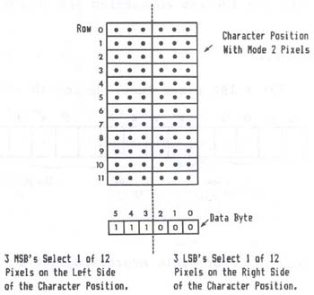
Mode 2 - Low Resolution Color This color mode is the highest resolution mode possible for NTSC composite video. The resolution in this mode offers you 128 pixels across the screen and 192 pixels down the screen. To give you an idea of the size of pixel we're talking about, the following figure shows the relationship between the mode 0 character position and the mode 2 pixel. Figure 7.3 - Mode 0 character position with mode 2 pixel outlined. As you can see, four vertically-stacked mode 2 pixels are equivalent to a mode zero graphics cell. To enter this mode in LNWBASIC, use the mode command, MODE 2 The mode 2 pixel can be displayed on the screen using this LNWBASIC program. Press BREAK to exit the program. 1 ' LNWBASIC program to display mode 2 pixel 10 MODE 2 : PCLS 2 : CLS 20 COLOR 5 : FLS REM FLS 'WHITES' MODE 0 SCREEN TO DISPLAY COLOR 30 PSET 63,97 40 CIRCLE 63,97,15 50 GOTO 50 To get the most of the computer's color capabilities in this mode, examine the COLOR, FLS and PCLS commands in the LNWBASIC manual. 
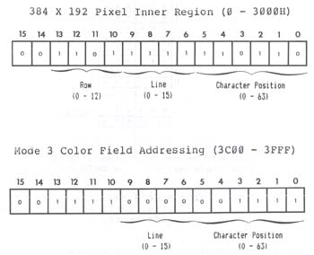
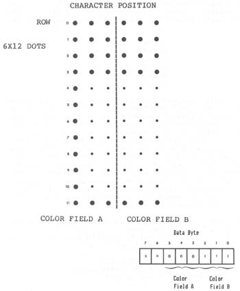
Mode 3 Graphics - High Resolution Color This high resolution graphics display mode allows the high resolution graphics monochrome (MODE1) information to be displayed on an RGB color monitor. This high resolution information is displayed with limited color control. This means that while the number of individually controllable color dots that can be displayed is 480H (horizontal) by 192V (vertical), the colors that they can be set to are limited to 128H by 16V color fields. These color fields have a relationship to. the high resolution position such that one color field controls the color of 36 high resolution pixels (dots). Color information is provided by the MODE0 text memory (memory from 3C00H to 3FFFH). The data stored in a given character position will determine the color of the high resolution graphics at that position. To better understand this, we will run the following program in LNWBASIC: 10 MODEl:PCLS:CLS' set to high res and clear all screens 20 LINE 0,3,383,3,SET ' draw high res line 30 MODE3 ? note the line above can be drawn in mode 3 also 40 FORC=0T07 ' step through all the colors 50 FOR I=0 TO 3'PUT EACH COLOR FIELD FOUR TIMES 60 AD=&H3C00+C*4+I? COLOR FIELD ADDRESS 70 POKEAD,C*9 'must use poke to output 80 NEXT I 90 NEXTC 100 GOTO 100 'wait forever and do not disturb screen When this program is run with a monochrome monitor installed, a high res (MODE1) LINE is drawn across the top of the screen, followed by characters overlapping the line on the screen. If we install an RGB monitor to the LNW80 now, we would see that the various characters cause the line to change colors. This overlapping of characters with high resolution graphics is how MODE3 graphics works. You might have noticed that after the color bars there was a blank space (color black) and then the rest of the line is displayed as alternating violet and white dots. Each of these dots represents the width of the smallest unit of color field which is one-half of a character position. This example used an entire character position as a color field with four consecutive color fields set to the same color. If we wanted to use the maximum color resolution, we could change the program to the following: 10 MODE1:PCLS:CLS? set to high res and clear all screens 20 LINE 0,7,479,11,SET,BF ' draw a high res line 30 MODE3 ? note the line above can be drawn in mode 3 also 40 FOR I=0 TO 15 50 FORC=0T07 ' step through all the colors 60 IF(C AND l)=0THEN90ELSE70 'is the pixel even or odd? 70 AD=INT(C/2)+I*4:D=PEEK(6H3C00+AD)?ODD find address and get data 80 D=DAND&H38:D=DORC:POKE(6H3C00+AD),D:GOT0110 'mask upr 3 bits, output 90 AD=INT(C/2)+I*4:D=PEEK(aH3C00+AD)'EVEN find address, get data 100 D=DAND7:D=DOR(C*8):POKEfaH3C00+AD),D'mask, or data, output 110 NEXTC 120 NEXTI 130 FOR Z=1T01000:NEXTZ 140 LINE 0,0,479,11,SET,BF 150 GOTO 150 This program draws a high res bar that extends beyond 383, and you should have noticed on the monochrome monitor that the characters that appear above the high res bar change the color of the bar on the RGB color monitor. Note that characters do not appear above the bar beyond character position 64 or high res position 383. Run the program again and watch the extension region while the inner region is writing the color fields. You will see that while colors are written to the inner region there is a duplication into the outer region. Due to the design of the hardware, the color information for any horizontal position past 383 is taken from color information from the same vertical position but from an assortment of horizontal positions (with values less than 383). This means that. if you use high resolution graphics beyond 383, you cannot be guaranteed the color unless all the color fields for pixels less than 383 are set to the same color. Mode 3 With LNWBASIC The initial release of LNWBASIC does not totally support MODE3 graphics. The mode command will set the LNW80 to the correct setting, but lines drawn in MODE3 are the same as lines drawn in MODEl with no color information provided. Later versions of LNWBASIC (if you registered with MODULAR SOFTWARE ASSOCIATES, you will be notified when this new version is ready) will fully support MODE3. In order to use the high resolution capability at this time, special subroutines must be written to write the color fields to match the high res graphics of LNWBASIC. The following programs provide rudimentary routines to fill fields and do limited line drawings in MODE3. 1 'THIS PROGRAM CONTAINS 3 MODULES. THE FIRST STARTING AT LINE 10 WILL DRAW A SINGLE LINE FROM 0,0 TO 383,191 AND THEN USE A COLOR FIELD TO MAKE THE LINE A GIVEN COLOR 2 ?THE SECOND MODULE (AT LINE 200) IS A DEMONSTRATION OF THE WAY LINES CAN BE DRAWN AND MADE TO HAVE A SPECIFIED COLOR USING MODE 3. THE ACTUAL SUBROUTINE TO DRAW THE LINE IS LOCATED AT LINE 1000 3 ?THE THIRD MODULE IS A DEMONSTRATION OF THE ABILITY TO CREATE BLOCKS OF COLORS. IT STARTS AT LINE 300. THE ACTUAL ROUTINE TO CREATE BLOCKS IS FOUND AT LINE 1000. NOTE THAT THIS THIRD MODULE DOES REQUIRE MODULE 2. 4 'IF ALL THIS SEEMS TERRIBLY CLUMSY- IT IS. THE FIRST RELEASE OF LNWBASIC DID NOT HAVE ANY MENTION OF MODE3 LATER RELEASES OF LNWBASIC WILL ALLOW THE USER THE ABILITY TO DRAW LINES' BOXES' CIRCLES' ETC IN MODE3 5 ?NOTE THAT THE PROGRAM TO DRAW LINES IS TERRIBLY INACCURATE 10 INPUT"COLOR";C 20 INPUT"X";X:INPUT"Y";Y 30 CLS 40 PCLS 50 MODE3 60 LINE 0,0,383,191,SET 70 MODE3 80 FLS(191) 90 POKE (&H3C00+Y*64+X),C*9 100 FOR X=1 TO 64 110 Y=INT(X/4) 120 POKE (6H3C00+Y*64+X),C*9 130 NEXTX 140 GOTO 140 200 'THIS DEMONSTRATES DRAWING A MODE 3 LINE 210 FOR P=1 TO 10 220 GOSUB 510 230 GOSUB 1040 240 NEXTP 250 GOTO 250 300 'THIS DEMONSTRATES DRAWING BLOCKS OF COLORS IN MODE3 310 FOR P=1 TO 10 320 GOSUB 510 330 GOSUB 2000 340 NEXTP 350 GOT0350 510 Xl=RND(383):X2=RND(383):Yl=RND(191):Y2=RND(191):C=RND(7) 515 RETURN 1000 REM THE FOLLOWING ROUTINE DRAWS A LINE OF A SPECIFIED COLOR IN MODE3 1010 INPUT"DESIRED COLOR";C 1020 INPUT"Xl,Yl";Xl,Yl 1030 INPUT"X2,Y2";X2,Y2 1040 MODE1 1050 CLS:PCLS:LINE Xl,Yl,X2,Y2,SET 1055 GOSUB 1060 1056 GOTO 1075 1060 Xl=INT(X1/6+.5):X2=INT(X2/6+.5):Yl=INT(Yl/12+.5):Y2=INT(Y2/12 +.5) 1070 IF Xl>63THENX1=63ELSE:IFX2>63THENX2=63ELSE:IFYl>15THENY1=15ELSE: IFY2>15THENY2=15 1072 RETURN 1075 IF100*Xl+Yl>100*X2+Y2 THEN T=Xl:Xl=X2:X2=T:T=Yl:Yl=Y2: Y2=T 1080 IF Xl=X2THENGOT01090ELSEGOT01100 1090 MODE3:FORY=YlTO Y2:POKESH3C00+Y"64+Xl,C*9:NEXTY:GOT01210 1100 M=(Y2-Yl)/(X2-Xl) 1110 B=Yl-M*Xl 1120 MODE3 1125 IFM>0 THENIFM<=1THEN1130ELSE1300 ELSEIFM>=-1THEN1130ELSE1350 1130 FORX=X1TOX2-1 1140 Y=INT((M*X+B)+.5) 1145 GOSUB1150 1146 NEXTX:RETURN 1150 Z=&H3C00+Y*64+X:IFZ<&H3C00ORZ>6tH3FFFTHENGOT01210 1160 POKE Z,C*9 1165 IF(X-2)>=0THENPOKE(&H3C00+Y*64+X-l),C*9 ELSEGOT01170 1170 IF(X-l)>0THEN POKE(&H3C00+Y*64+X-1),C*9 ELSEGOT01180 1180 IF(X+1)<65THENPOKE(&H3C00+Y*64+X+l),C*9 ELSEGOT01190 1190 IF(X+2)<64THENPOKE(&H3C00+Y*64+X+2),C*9 ELSE GOT01200 1200 RETURN 1210 RETURN 1220 Xl=0:Y1=0:X2=63:Y2=15 1230 MODE1 1240 LINE 0,0,377,179,SET 1250 MODE3 1260 GOTO 1100 1300 FORY=Y1TOY2'SLOPE BETWEEN -1 AND 1 1310 X=INT((Y-B)/M+.5) 1320 GOSUB 1150 1330 NEXTY 1340 RETURN 1350 T=Y1:Yl=Y2:Y2=T? SLOPE BETWEEN -1 AND -INFINITY 1360 GOT01300 2000 IFXl=X2THEN1050ELSEIFYl=Y2THENGOT01050 2010 LINE Xl,Y1,X2,Y2,SET,B 2020 M0DE3 2030 GOSUB 1060 2040 IFY1<Y2THEN2060 2050 T=Y1:Yl=Y2:Y2=T 2060 IFXl<X2THEN2080 2070 T=X2:X2=X1:X1=T 2080 IFY1=0THENY1=1ELSE:IFX1=0THENX1=1 2090 FORY=Y1-1T0Y2:FORX=X1-1TOX2:POKE&H3C00+Y*64+X,C*9:NEXTX:NEXTY 2100 RETURN High Resolution Graphics for Non-Disk Owners The program listed below sets up tables in memory which hold information on the coordinates of points to be SET, RESET or POINTed. (The machine-language program encoded in the DATA statements is listed at the end of this section). 0 REM This program POKES 2 tables into memory. The first one 1 REM generates 2 bytes for each horizontal coordinate (X). 2 REM This two byte pair consists of (a) the character 3 REM position (0-79) and (b) the one of six pattern 4 REM selecting the pixel within the character position. 5 REM The second table gives the vertical coordinate. It 6 REM consists of 192 locations each of which holds the 7 REM row (D4-7) and the line (D0-3).The tables start at 8 REM 30000. 10 X=30000 20 FOR Y=0 TO 79 30 GOSUB 100 40 NEXT Y 50 X=31024 55 FOR L=0 TO 15 60 FOR R=0 TO 11 65 N=(16*R)+L 70 POKE X,N 75 X=X+1 80 NEXT R 85 NEXT L 90 GOTO 171 100 N=l 101 FOR Z=0 TO 5 120 POKE X,Y 130 X=X+1 140 POKE X,N 150 X=X+1 155 N=N*2 160 NEXT Z 165 RETURN 166 REM This routine POKES the machine-language USR program 168 REM (encoded in the DATA statements) into RAM from 167 REM location 79F0H (31216) to 7A90H (31376) 169 REM (31376). 171 FOR X=31216 TO 31376 172 READ Y 173 POKE K,Y 174 NEXT X 175 REM The POKE command at line 200 gives the entry point of 177 REM the one USR call. The low order byte must be changed 179 REM to point to one of the other routines if desired: 185 REM To select SET,RESET,POINT use the following values: 187 REM SET - POKE 16526,240:POKE 16527,121 189 REM RESET - POKE 16526,243:POKE 16527,121 191 REM POINT - POKE 16526,246:POKE 16527,I21 182 REM Remember that these address locations are decimal. 193 REM Once you have POKEd these values out, you need only 195 REM POKE the LOW ORDER BYTE to change to a different 197 REM routine (e.g. POKE 16526,246 gives POINT). 199 REM 200 POKE 16526,240:POKE 16527,121 ' SET Routine 210 CLS ?Clears LORES screen 220 OUT 254,2 'Turns HIRES (Mode 1) on 230 FOR X=0 TO 479 'Bumps through all X 240 FOR Y=0 TO 191 'Bumps through all Y 250 POKE 31257,Y ?POKES Y value to 31257 (in USR) 260 A=USR(X) 'X is passed to USR routine 270 NEXT Y 280 NEXT X 290 END 300 DATA 195,67,122,195,88,122,195,113,122,205,127,10 310 DATA 1,48,117,4lg9,126,254,64,242,35,122,205,19,122 320 DATA 203,60,203,29,203,60,203,29,201,35,70,33,48,121 330 DATA 17,0,0,25,102,111,203,37,203,37,201,205,19,122 340 DATA 203,37,203,37,203,4,203,4,203,60,203,29,203,60 350 DATA 203,29,203,60,203,29,203,60,203,29,124,198,48 360 DATA 103,20l,205,249,121,219,254,246,8,211,254,126 370 DATA l76,ll9,219,254,230,247,211,254,195,154,10,205 380 DATA 249,121,219,254,246,8,211,254,120,238,255,71 390 DATA 126,160,119,219,254,230,247,211,254,195,154,10 400 DATA 205,249,121,219,254,246,8,211,254,126,160,194,133 410 DATA 122,33,0,0,195,l36,l22,33,1,0,219,254,230,247 420 DATA 211,254,195,154,10 Color Graphics for Non-Disk Owners The following listing demonstrates how to generate colors on the LNW80 without using LNWBASIC. 10 REM COLOR BAR TEST PROGRAM 20 REM CASSETTE (16K) VERSION 30 REM This test should generate the following colors: 35 REM White Green Yellow Red Magenta Blue Blue-Green Black 36 CLS:PRINTCHR$(23) 40 PRINT "LNW RESEARCH COLOR BAR TEST" 45 REM Delay before starting test 50 FOR Z=0 TO 1000 60 NEXT Z 70 OUT 254,4 72 FOR X=15360 TO 16383 74 POKE X,255 76 NEXT X 80 FOR X=32512 TO 32533 90 READ D 100 POKE X,D 110 NEXT X 120 POKE 16526,0:POKE 16527,127 125 FOR X=0 TO 12288 130 FOR Y=0 TO 7 135 FOR Z=0 TO 7 150 POKE 32522,Y*9 180 A=USR(X) 190 LET X=X+1 200 NEXT Z 210 NEXT Y 220 LET X=X-1 230 NEXT X 240 END 270 DATA 205,127,l0,219,254,246,8,211,254,54,0,0,110,38,0 280 DATA 230,247,211,254,195,154,10 GRAPHICS FOR MACHINE-LANGUAGE PROGRAMMERS Machine-Language Overview The four different graphics modes are selected by I/0 port 254 (FE Hex). The definition of port 254 is shown schematically in Figure 7.4.

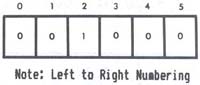
Figure 7.4 - 8 bit address of port 254 showing bit definition. Data bit 0 controls inverse video operation in modes 0 and 1 only. Data bits 1 and 2 together give mode control, as can be seen from Table 7.1. Table 7.1 - Mode Control Using Port 254

D2   D1
Mode
0    0
0 1
1 0
1 1
  0
1
2
3

   Data  bit  3 controls graphics RAM enable. Data bits 4 to 7
are reserved and should not be used.

   When  modifying  port  254,  first  read  the port and then
change only the bits that you want to change. As  an  example,
consider  the  following  LNWBASIC program (any level of BASIC
will do) which sets data bit 0 of port 254, thus changing over
to inverse video.

         1 ?PROGRAM TO SET DATA BIT 0 OF PORT 254
        10 A=IMP(254)
        20 A=1 OR A
        30 OUT 254,A

To return to normal white on black, substitute 0 for 1 in line
20.


Mode 0 Adressing

   Video  display  memory  for this mode runs from 15360 (3C00
Hex) to 16383 (3FFF HEX) . A two-byte address is used to point
to  a  location  in  video  RAM.  The relationship between the
memory location and the visibly displayed character is defined
by the following address chart:

Figure 7.5 - Mode 0 addressing as in p. 64 of original LNW manual. The least significant (rightmost) 6 bits, bits 0 to 5, of the address specify the character position. With all 6 bits on for example, character position 63 would be specified. Bits 6 to 9 inclusive store the binary code for the line (0 - 15) on which the character posit.3.on is found. Take, for example, address 3C97. Filling the address chart we get:

Figure 7.6 - Mode 0 address chart with 3C97 displayed. This translates to line 2, character position 23, as shown in Figure 7.7.

Figure 7.7 - Screen with character 23, line 3 highlighted. We have seen how screen positions are addressed and how both graphics characters and text characters are constituted. But how does the computer know whether a graphics character or a text character is to be displayed? The answer is encoded in the data byte to be displayed. When data bit 7 of the data byte is on, bits 0 to 5 select all possible combinations of graphics characters. With data bit 7 off, bits 0 to 5 are together interpreted as an ASCII text code. See figure 7.8.

Figure 7.8 - Data byte, 8 bits, bit 7 on/off - graphics/text respectfully. Bit 6 not used, bits 0 to 5 store code. Note that graphics RAM is not used in this mode. Accessing Graphics RAM Graphics modes I, 2 and 3 make use of graphics RAM. The graphics RAM, running from address 0 to 3FFF (hex), is located in the lower 16K of LNW80 address space. This is also where the the Level II ROMs, keyboard, mode 0 video RAM, and miscellaneous I/0 is mapped. I/0 port 254, data bit 3 (D3), selects which block of memory is enabled in the lower 16K. With D3 on (1), the graphics memory is enabled. With D3 off (0), the keyboard, video RAM, 12K ROM and anything else which might be mapped in the lower 16K of address space are enabled. Figure 7.9 illustrates this bank switching operation.

Figure 7.9 - Memory bank switching diagram Since the Level II ROMs are also disabled when D3 is on, using the out command in BASIC to turn this bit on will cause a system "crash." This is because the computer will be operating out of graphics RAM instead of ROM. The implication of this is that D3 can only be accessed by a machine-language program (or USR call from BASIC). Note that while the graphics RAM is enabled, the lower 16K is inaccessible. Mode 1 Addressing The high resolution graphics RAM is located between 0 and 3FFF (hex). The 16K x 6 bits of graphics memory allows individual control of 480 x 192 dots. The addressing is not simple X,Y addressing, but is optimized for rapid character generation, In this scheme of things, the video memory map is broken into two fegiona: an inner region comprised of 384 x 192 dots, and an extension region comprised of 96 x 192 dots. Figure 7.10 shows this screen breakdown.

Figure 7.10 - Screen inner and extension regions. The 384 x 192 inner region runs from address 0 to 2FFF (hex). The address chart for the inner region is as follows:

Figure 7.11 - Inner region address chart. The 96 x 192 extension region is addressed from 3000 to 3FFF (hex). The address chart for the inner region is given below. In this case, the row field has been divided in two: bits 10 and 11 holding the two least significant bits (LSB), and bits 4 and 5 holding the two most significant bits (MSB). This was done for hardware implementation reasons only.

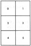
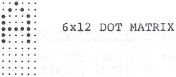
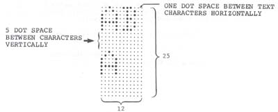
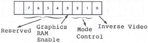
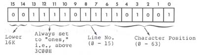
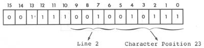
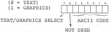
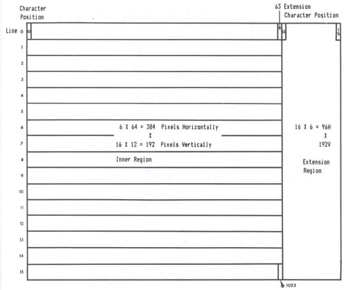
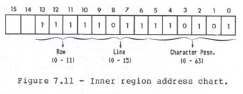
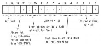
Figure 7.12 - Extension region addressing. We said that the addressing was not simple X,Y addressing. So what does that mean? An example will help to illustrate the situation. Take address 2000H. Going to the address chart and filling in 2000H, we get:

Figure 7.13 - Address chart with 2000H, and character position, line & row, marked. This takes us to row 8 of line 0, character position 0. This is a bit unexpected, as we have been used to the idea of starting at the top left hand corner of the screen and then addressing all points down the screen, in a contiguous fashion. If we start with address 0 and sequentially move through to address 2FFF, examining the positions pointed to on the screen by each address, we will see that row 0 of all character positions is addressed first, then row 1 of all character positions, then row 2... and so on. The same holds for the extension region. (Try a few examples). The information telling us which pixels are on in a particular row, comes from the 6 bit-datum byte located in graphics RAM:

Figure 7.14 - Graphics Data Byte in LSB (0-2) and MSB (3-5) Format Each bit in the byte corresponds to one of the pixels in the row, pointed to by the address we just deciphered. Mode 2 Addressing The mode 2 pixel differs from the mode l pixel in that it is 3 times larger, being composed of 3 horizontal dots, The loss of resolution is compensated for by way of color information for each pixel. Mode 2 addressing is similar to mode 1 inner region addressing (see Fig. 7.15). In this case however, the data byte holds information for two adjacent color pixels, each half of the byte containing three bits specifying one of 8 colors.

Figure 7.15- Mode 0 character position w/mode 2 pixel outlined, and data byte underneath. Bits 3, 4 and 5 contain color information for the pixels on the left hand aide of the character position. Bits 0, 1 and 2 contain color information for the right-hand side of the character position. The codes for the 8 colors available are as follows: Table 7.2 - Color coding for mode 2 pixels.

Data Color
000 White
001 Green
010 Yellow
011 Red
100 Magenta
101 Blue
110 Blue/Green
111 Black
Mode 3 Addressing

   A simple relationship exists between  the  high  resolution
video and the mode 3 color fields. This relationship is due to
the fact that the low res text memory and the high res  memory
share  the  same  addressing in the hardware. The inner region
addressing and the low res addressing are compared below:

      Figure 7.16

It should be noted that the character position of the MODE3 color field addressing is divided into two color fields. When a byte is written to 3C00H to 3FFFH, two color fields are set as illustrated below: Figure 7.17 Mode 3 Character Position With Color Fields

WITH COLORS DEFINED AS: 5 4 3 or 2 1 0 ---------- 0 0 0 0 white 0 0 1 1 green 0 1 0 2 yellow 0 1 1 3 red 1 0 0 4 magenta 1 0 1 5 blue 1 1 0 6 blue-green 1 1 1 7 black The second LNWBASIC program in this section illustrates how MODE 3 graphics is done from BASIC. Once this is clearly understood, machine-language use should be simple. When using MODE 3 to draw lines, circles, etc., setting the correct color field can be easily done at the same time that the machine-language routine is outputting to the high res screen. If the high res address has been computed or looked-up via some form of address computation table, this address needs only to have the most significant 6 bits masked and set as follows: A15=0 A14=0 A13=1 A12=1 All=1 A10=1 The only additional consideration is which color field is to be written at that character position? Is it color field A or B? The software that writes the high res information must have some method of knowing which high res data bit was the one that was being written to. If the data bit(s) of the high res memory was 0, 1 or 2 (the leftmost 3 dots on the screen) then the color field to be written to is color field A. If the data bit(s) of high res are 3, 4 or 5 (the right three bits) then the appropriate color field is B. In order to write only the desired color field, the program must first read the entire byte (both color fields) with masking and ORing to put the 3-bit color information in the right place without disturbing the other color field. Refer to the LNWBASIC program in the above section for the conceptual details. Remember that when the high res video memory is enabled via port 254 data bit 3, the low res video memory 3C00 to 3FFFH is not accessible. This means that before writing the color field you must turn off the graphics enable as follows: IN A,(0FEH) ; INPUT FROM 254 AND 0F7H ; TURN OFF GRAPHICS RAM OUT (0FEH),A ; OUTPUT TO 254 Then the graphics mode must again be turned on before writing more graphics. Machine-language Routine to SET, RESET, POINT The following is the machine-language listing to SET, RESET or POINT a video RAM location. This is the listing for the machine-language that was encoded in the DATA statements in the program listed under the subsection entitled "Graphics for Non-Disk Owners." 79F0 00100 ORG 79F0H 79F0 C3437A 00101 SET JP SETR ;SET ROUTINE ENTRY 79F3 C3587A 00102 RESET JP RESR ;RESET ENTRY 79F6 C3717A 00103 POINT JP POIR ;POINT ROUTINE 79F9 CD7F0A 00110 ADCAL CALL INPX GET X POSITION IN HL PAIR 79FC 013075 00120 LD BC,7530H ;START OF HORIZONTAL TBL 79FF 29 00125 ADD HL,HL ;DOUBLE HL IN TABLE 7A00 09 00130 ADD HL,BC ;POINT TO CHARACTER POS. IN TBL 7A01 7E 00140 LD A,(HL) ;INPUT CHARACTER POSITION 7A02 FE40 00150 CP 64 ;IS > THAN CHAR 64 (IN EXTENSION) 7A04 F2237A 00160 JP P,EXTEND ;YES USE EXT. ALGORlTHM 7A07 CD137A 00170 CALL VERT ;GET ROW.LINE,CHARACTER ADJUSTED 7A0A CB3C 00180 SRL H ;SHIFT LSB OF H INTO CARRY 7A0C CB1D 00190 RR L ;GET LSB OF H INTO MSB OF L REG 7A0E CB3C 00200 SRL H ;SHFT LSB OF H INTO MSB OF L 7A10 CB1D 00210 RR L ;ONCE AGAIN 7A12 C9 00220 RET ;NOW HL HAS ADDRESS OF GRAPHICS 7A13 23 00240 VERT INC HL ;THlS PUTS ROW.LINE INTO H AND 00245 ;PUTS CHARACTER POSITION SHIFTED 00247 ;LEFT TWO BITS INTO L WITH THE 00249 ;TWO LSB SET TO ZERO 7A14 46 00250 LD B,(HL) ;NOW B REG HAS ONE OF SIX PATERN 7A15 213079 00260 LD HL,7930H ;START OF VERTICAL LOOKUP TABLE 7A18 110000 00265 LD DE,0H ;POKE DATA HERE 7A1B 19 00270 ADD HL,DE ;POINT TO VALUE IN TABLE 7A1C 66 00280 LD H,(HL) ;PUT ROW.LINE INTO H 7AlD 6F 00290 LD L,A ;COPY CHARACTER POSITION TO L 7A1E CB25 00300 SLA L ;SHIFT LEFT ONE PLACE 7A20 CB25 00310 SLA L ;NOW L HAS LEFT JUSTIFIED CHAR 7A22 C9 00320 RET 7A23 CD137A 00330 EXTEND CALL VERT ;GET VERT IN H,CHAR IN L,DAT IN B 7A26 CB25 00340 SLA L ;ROTATE 2 MSB OF ROW AND 7A28 CB25 00350 SLA L ;PUT THEM IN THE 2 LSB OF H 7A2A CB04 00360 RLC H 7A2C CB04 00370 RLC H 7A2E CB3C 00375 SBL H ;NOW SHIFT HL RIGHT 4 PLACES 7A30 CB1D 00380 RR L 7A32 CB3C 00398 SRL H 7A34 CB1D 00400 RR L 7A36 CB3C 00410 SRL H 7A38 CB1D 00420 RR L 7A3A CB3C 00430 SRL H 7A3C CB10 00440 RR L ;HL OK NOW 7A3R 7C 00445 LD A,H 7A3F C630 00447 ADD A,30H ;MAKE ADDRESS ABOVE ROW 11 7A41 67 00449 LD H,A 7A42 C9 00460 RET 7A43 CDF979 00478 SETR CALL ADCAL 7A46 DBFE 00480 IN A,(0FEH) ;INPUT FROM 254 7A48 F688 08498 OR 8 ;TURN ON GRAPHICS RAM ENABLE BIT 7A4A D3PE 00500 OUT (0FEH),A ;OUTPUT TO 254 7A4C 7E 00510 LD A,(HL) OLD DATA IN A REG 7A4D BS 80520 OR B ;SET BIT 7A4E 77 00530 LD (HL),A ;WRITE DATA BACK OUT 7A4F DBFE 00540 IN A,(0FEH) ;INPU AGAIN 7A51 E6F7 00550 AND 0F7H ;TURN OF GRAPHICS RAM 7A53 D3FE 00560 OUT (0FEH),A ;OUTPUT PORT 254 7A55 C39A0A 00570 JP RETURN 7A58 CDF979 00580 RKSR CALL ADCAL 7A58 DBFE 00590 IN A,(0FEH) ;INPUT PORT 254 7A5D F608 00600 OR 8 ;SET GRAPHICS RAM ENABLE BIT 7A5F D3FE 00610 OUT (0FEH),A ;OUTPUT TO PORT 254 7A61 78 00620 LD A,B 7A62 EEFF 00630 XOR 0FFH ;COMPLEMENT A 7A64 47 00640 LD B,A 7A65 7E 00650 LD A,(HL) 7A66 A0 00660 AND B 7A67 77 00670 LD (HL),A ;WRITE DATA BACK OUT 7A68 DBFZ 00688 IN A,(0FEH) ;INPUT AGAIN 7A6A EGF7 00690 AND 0F7H ;TURN OFF GRAPHICS RAM 7A6C D3FE 00700 OUT (0FEH) ,A 7A6E C39A0A 00710 JP RETURN 7A71 CDF979 00720 POIR CALL ADCAL 7A74 DBPR 00730 IN A,(0FEH) 7A76 F608 08748 OR 8 7A78 D3FE 00750 OUT (0FEH),A 7A7A 7E 00760 LD A,(HL) ;GET SIX BITS OF DATA 7A7B A0 00770 AND 8 ;MASK ALL BUT SELECTED BIT 7A7C C2857A 00780 JP NZ,SETHL ;MAKE L=l IF NOT ZERO 7A7F 210000 00790 LD HL,0H ;MAKE BL PAIR 0 7A82 C3887A 00800 JP QUIT ;EXIT 7A85 210100 00810 SETHL LD HL,1H ;SET HL=00018 7A88 DBFE 00812 QUIT IN A,(0FEH) ;INPUT PORT 7A8A E6F7 00814 AND 0F7H ;TURN OFF GRAPHICS RAM BIT 7A8C D3FE 00816 OUT (0FEH),A ;0UTPUT TO PORT 254 7A8E C39A0A 00820 JP RETURN 0A9A 00838 RETURN EQU 0A9AH 0A7P 00840 INPX EQU 0A7FH ;THIS PUTS VARIABLE INTO HL 0000 00850 END 00000 TOTAL ERRORS Next page | TOC