By Ciarán McManus First Edition - October, 1982 All rights reserved. Reproduction or use, without express permission is prohibited. While every effort was taken in the preparation of this book, the publisher assumes no liability for errors or omissions. Neither is any liability assumed for damages resulting from the use of the information contained herein. Copyright © 1982, LNW RESEARCH CORP. TABLE OF CONTENTS SECTION 0: INTRODUCTION TO THE LNW80 OWNERS' MANUAL ...... 5 * Documentation * What is a Computer? * I/0 Devices * CPU * Memory * Computer Languages * What is an Operating System? * Utility Programs * Application Programs SECTION 1: UNPACKING THE HARDWARE ....................... 13 SECTION 2: DESCRIPTION OF THE LNW80 ..................... 14 * General Description * Keyboard * Changing Key Definition * Z80A Microprocessor * ROM * RAM * Parallel Printer Interface * Cassette Interface * RS232C Interface * Floppy Disk Controller * I/0 Panel SECTION 3: VIDEO DISPLAY ................................ 22 * Introduction * Monitors for the LNW80 * Connecting a Monitor * Connecting an RGB Monitor * Using the Monitor With BASIC SECTION 4: CASSETTE INTERFACE ........................... 27 * Hooking up a Cassette Recorder * Using a Cassette Recorder * Transfer Speed * Saving a BASIC Program * Loading a BASIC Program * So, it Won’t Load * Verifying a Load * Loading a Machine-language Program * Lower-case with Cassette Based System * Complete Lower-case Program SECTION 5: DISK INTERFACE ............................... 33 * Introduction * What Kind of Disk Drives You Should Use * Configuring 5-1/4" 6 8" Drives * Connecting a 5-1/4" Drive * Connecting 8" Drives * Disk Drive Set-up 6 the 5/8 Switch * Other Considerations * Disk Descriptions * Disk Care SECTION 6: POWER ON ..................................... 41 * Connecting AC Power * Power-up 6 Reset for Non-Disk Owners * Power-up a Reset for Disk Owners * Disk Power-up Malfunctions * Monochrome Monitor Adjustments * NTSC Monitor Adjustment * Monochrome Operation * Color Operation * RGB Monitor Adjustment a Operation * Power Off * Memory Test * High Speed / Low Speed Test * Graphics Test SECTION 7: LNW80 GRAPHICS ............................... 47 * Introduction * Graphics Modes * Mode 0 * Mode 1 * Mode 2 * Mode 3 * Machine-language Overview * Mode 0 Addressing * Mode 1 Addressing * Mode 2 Addressing * Mode 3 Addressing SECTION 8: LINE PRINTER INTERFACE ....................... 70 * Line Printer Types * Outputting to the Printer Using BASIC * Page Length * Line Count * Printer Availability * Adjusting Printer Controls SECTION 9: RS232C INTERFACING ........................... 74 * History of Serial Data Communication * RS232C Standard * RS232C Operation * Connecting Equipment to the RS232C * The Baud * Transmission Techniques * Transmitting and Receiving * Setting Transmit and Receive Rates * Setting Parity * Setting Word Length * Setting Stop Bits * Getting the Most From RS232C * Modem SECTION 10: MEMORY UTILIZATION .......................... 90 * A Look at Memory in a Non-disk System * A Look at Memory in a Disk System * High Memory Protection SECTION ll: CHOOSING AND USING A DISK OPERATING SYSTEM .. 92 * Introduction * Important Aspects of o DOS * Brief History of TRS80 Model I Operating Systems * Looking at the Various DOSes * Top Five DOSes * TRSDOS 2.3 * DOSPLUS 3.4 * NEWDOS80 2.0 * LDOS 5.0/5.1 * MULTIDOS SECTION 12: COMPATIBILITY FEATURES OF THE LNW80 ......... 106 * DOSPLUS 3.4 CONVERT Command * LNWBASIC 6 TRS EXTENDED COLOR BASIC SECTION 13: LNW80 DETAILED DESCRIPTION & SPECIFICATIONS . 111 * General * CPU * Memory * Keyboard * MICROSOFT BASIC Interpreter * Other Features * Video Display Specifications * Floppy Disk Interface * Printer Interface * Cassette Interface * RS232C Interface * Terminal Emulation Capability * Expansion Port * Real-time Clock * LNWBASIC SECTION 14: SHOOTING TROUBLE ............................ 120 * Symptoms, Causes, Cures * Outside Interference APPENDIX A: A BUYER’S GUIDE TO MONITORS ................. 122 * Introduction * Monochrome Monitors * Recommended List of Monochrome Monitors * NSTC Video Color Monitors * RGB Color Monitors APPENDIX B: DISK DRIVE TUTORIAL ......,....,............. 125 * The History of the TRS-80 Disk * Termination Resistors * Drive Selection & Pulled Pin Cables * Double-sided Disk Drives * Double-density Catches On * Configuring 5-1/4" Disk Drives * Eight-inch Drives * Configuring 8" Disk Drives APPENDIX C: MODE 1 DRAWING PROGRAM ...................... 139 APPENDIX D: VIDEO DISPLAY DIAGRAM ....................... 142 APPENDIX E: GLOSSARY .................................... 145 INDEX: .................................................. 157 USER'S RESPONSE SHEET ................................... 167 SECTION 0: INTRODUCTION TO THE LNW80 OWNER MANUAL Congratulations! You have purchased one of the finest personal and small business computers available - the LNW80. The LNW80 is software and hardware compatible with the TRS80 Model I computer. This means that one of the largest and most mature libraries of software will run on the LNW80 without modification. It also means that a huge selection of hardware accessories, such as disk drives, printers, printers, modems, video monitors, data acquisition equipment and much more will plug right in and run. But the LNW80 is more than just a TRS80 work-alike. The LNW features high resolution graphics, color, the interfaces for RS232, 5" and 8" single and double-density floppy disk drives, printer and cassette. The LNW80 comes complete with 12K ROM, 48K RAM and a 74-key keyboard with numeric entry pad. The LNW80 also comes complete with the DOSPLUS 3.4 Disk Operating System (TRSDOS compatible), Advanced Disk Basic (LNWBASIC) and complete documentation. It is housed in a sleek steel case with a cooling fan for increased reliability. This owner manual was written to make your first experience with the LNW80 a pleasant one. It also provides the link between your computer and the following other documentation: 1. Level 2 BASIC Manual Level 2 BASIC is the microsoft BASIC-88 interpreter written for the LNW80. It is the BASIC which is compatible with the TRS-80 Model I LEVEL 2 computer. This BASIC is "BUILT IN" to the LNW80 and is permanently stored an ROM. 2. DOSPLUS 3.4 Disk Operating System Manual DOSPLUS 3.4 is a DOS (Disk Operating System) which is compatible with TRSDOS (Model I). It is authored by Microsystem Software Inc. 3. LNWBASIC Advanced Disk BASIC Manual LNWBASIC (written by Nodular Software Associates) is an extension to the Disk BASIC Interpreter supplied in DOSPLUS 3.4, or to NEWDOS80 version 2.0, LDOS 5.1 and TRSDOS 2.3. This is the part that has graphics, color, programmable key functions and some other advanced features. 4. LNW80 Technical Reference Manual This ls the Service manual for the LNW80. This manual is intended for those technically- inclined individuals. Theory of operations, logic diagrams, trouble-shooting tips, test programs, parts lists, disaasembly and re-assembly instructions are provided. If you are a first-time computer owner -- sit back, relax and read the following section before proceeding to tear the wrapping off your LNW80 computer. If you have owned a TRS-80 or another personal computer (or if you just cannot wait to get your hands on your LNW80) proceed to section 1, entitled "Unpacking the Hardware". What is a Computer? Twenty years ago, the word "COMPUTER" meant an air-conditioned room full of electronics costing millions of dollars. Today the word "computer" can mean anything from a 10 million dollar mainframe computer to the "chip" inside the electronics of your microwave oven. A computer is a machine which can automatically do arithmetic and make logical decisions. Input Output (I/0) Devices The computer can also make data available to and from us via input and output, devices. A KEYBOARD (typewriter style keys) is an INPUT device because it allows us to type information into the computer. This information can then be used by the computer to tell it what you want it to do, or it could be data for calculations or even a typed letter. An OUTPUT device is one that allows the computer to make information available to us. A video display is an output device because it allows the computer to "write" to us via the display screen. This display is fast and can be written over and over again, It has a disadvantage that there is no permanent "record" of this information. Once it "ROLLS" off the screen (SCROLLS), it is lost. A printer is also an output device. It "writes" on paper the information that the computer would like to communicate to us in a more permanent manner. Central Processing Unit (CPU) To make a computer useful, we must have input devices, output devices, and we must perform computations (arithmetic and logical decisions). The device which performs the computation is called the "CENTRAL PROCESSING UNIT" or CPU. The CPU in the LNW80 is the Z80A MICROPROCESSOR. It is the world's most popular 8-bit microprocessor (small processor) and can do thousands of computations in one second. In order for the CPU to do computations, the CPU must be told what it should do in a step-by-step fashion. Each step is an addition, subtraction, logical operation, or input/output operation. These step-by-step operations are called "instructions," or to be more exact, MACHINE LEVEL INSTRUCTIONS. Memory These instructions are stored in main computer storage before being executed. The main computer storage is called MEMORY. Memory as analogous to 65536 mailboxes in a row on a very long street. Each mailbox has an address marked on it from 0 to 65535. Each mailbox may look different on the outside, but can only hold the same amount of materia1 inside. Each location of a mailbox as called a "memory location," or "memory ADDRESS". For an 8-bit CPU, each address can contain a number from 0 to 255. This corresponds to 2 to the eighth power or 2exp(8) or 2x2x2x2x2x2x2x2=256. The reason that there are 65536 memory locations as due to the memory addressing capability of the Z80 microprocessor. Most of the eight-bit microprocessors have this home addressing capability. Smaller CPU's (4-bit) address fewer locations, and larger CPU's (minicomputers and some 16-bit. CPU’s) can address much larger memories (sometimes millions of locations). The advantage of larger memories is the ability to have much larger programs. Since memory is not cheap, this does cost money. There are techniques of storing large programs in modules so that only a few modules need to be in main computer storage at any time, thus allowing larger programs to run in a smaller address space. This as called memory management, or as it is more commonly referred to an the microcomputer world - OVERLAYS. OVERLAYS are just come of the programming techniques made easy by LNWBASIC, and DISK BASIC. In the LNW80, memory takes two different forms. There is ROM (Read Only Memory) which as a "hard wired" memory that cannot be changed, and there is RAM (Random Access Memory - also called Read/Write Memory), which can be changed, but will disappear when power is removed from the computer. Instructions, when executed as a group to perform a desired function are called PROGRAMS. Computer Languages Just as people developed a variety of languages to communicate with each other, so there would become a variety of languages to communicate with computers. COMPUTER LANGUAGES are machine level programs that make communication between us and computer easier. Hundreds of computer languages have been developed, and with time, even dialects of languages developed. Cobol, Snobol, Algol, Fortran 4, Fortran 77, BASIC, Tiny BASIC, Extended BASIC, Level 2 BASIC, Disk BASIC and Advanced Disk BASIC are dialects of some fundamental computer languages. These languages are called HIGH-LEVEL LANGUAGES. By high-level we mean that a single high-level language instruction is translated into multiple machine-level instructions. This reduces the amount of time required to tell the computer what to do - which simplifies programming. This translation can occur during the time that the program is being run (RUN-TIME), or the translation can be done in advance, with the final translated version of the program (COMPILED OBJECT CODE) stored for later execution. A run-time translator is known as an INTERPRETER. One of the advantages of an interpreted high-level language is the reduced memory requirement for storing and executing the program. Since the high-level language is in memory during the execution, the program also can take advantage of the error recovery facilities of the high-level language. This makes interpretive languages qenerally easier to program and easier to get the "bugs" out of the program (DEBUG) to make it operational. All the levels of BASIC supplied with the LNW80 are interpretive. A translator that does the translating in advance of execution is commonly referred to as a COMPILER. A compiler has the advantage of execution speed since it has all the instructions, translated in advance and can directly execute the translated instructions. Assembly-Language Assembly-language was the first of the computer languages developed. It allows symbolic notation to represent machine-language instructions. This makes for an easier way of programming machine level instructions. This is sometimes confusing to first-time computer owners, since much literature is written using the terms MACHINE-LANGUAGE and ASSEMBLY- LANGUAGE interchangably. The program that compiles the assembly-language program is called an ASSEMBLER. For more details concerning assembly-level programming, we recommend the following book, available from Radio Shack: TRS80 Assembly-Language Programming by William Barden Jr. BASIC The most popular language used on the LNW80 computer is BASIC. BASIC (Beginner's All-purpose Symbolic Instruction Code) was developed at Dartmouth College in 1965. It has since become the most widely used language of microcomputers and small business computer systems. Both interpretive and compiled forms of BASIC are commonly used. The LNW80 is supplied with four levels of interpretive BASIC: 1. Level II BASIC (FOOTNOTE - if you are wondering what happened to level 1, it is a small, very limited BASIC that was originally sold on the TRS80 Model I and Model III) occupies 12K (12 X 1024) bytes of memory, and is permanently stored in ROM. It has full line editing features, string variables, multiple dimension arrays, 14-digit accuracy, low resolution graphics, cassette I/0, Video I/0, Printer I/0, scientific functions, string-handling operations, etc. 2. DOSPLUS 3.4 TINY DISK BASIC - This is supplied on the DOSPLUS 3.4 diskette and provides an extension to the above BASIC. It adds floppy disk file handling, advanced keyboard I/0, in-string search command, programmer-defined BASIC instructions, and loading, saving, killing, merging BASIC programs to and from the floppy disk drive. 3. DOSPLUS 3.4 EXTENDED DISK BASIC - This BASIC adds to the above BASIC the following features: 1. Execute DOS commands from BASIC 2. Advanced editing features 3. Program line renumbering 4. BASIC array sort verb 5. Controlled screen input routine 4. LNWBASIC Advanced Disk BASIC - This adds even more commands to the above BASIC and is supplied on a 35-track single-density data disk. It can be used with either Extended Disk BASIC or Tiny Disk BASIC. It adds up to 40 new commands to BASIC. It has a "creator" mode which allows the programmer to create the BASIC he wants by selecting from a menu of new commands which include: 1. High resolution graphics and color commands 2. Programmable keyboard features 3. Programming shorthand notation 4. Machine Language "CALL" command 5. Sound command 6. RS232 communications from BASIC 7. Printer Spooler 8. Execute string as BASIC statement 9. Block and blinking cursor 10. Do/Until Construct and Much more... BASIC Compilers There is quite a variety of BASIC Compilers available for the LNW80 computer. The biggest disadvantage of most of these compilers is the lack of compatibilty with their interpretive counterparts. The Compiler BASIC available from Radio Shack is not compatible at all. The Microsoft BASIC Compiler (for the R/S Model I) is almost completely compatible with the DOSPLUS 3.4 Tiny Disk BASIC (including disk I/0), but it does have its limitations and cannot take advantage of some of the advanced features of DOSPLUS 3.4 Advanced Disk BASIC or LNWBASIC. There are other compilers that vary in price and features end can be found advertised in the computer magazines or available from your local computer dealer. Other Languages One of the reasons for the many computer languages is that the high-level language programmers have different needs as to the high-level instructions they would prefer to use. For example, scientific applications require fast data computation, scientific accuracy, easy formula evaluation and special scientific functions (trigonometry functions, etc.) FORTRAN (FORmula TRANslation) provides this by having instructions which can do these types of functions easily. Fortran is not a good language for business since it does not have some of the high-level instructions for manipulating business data. Cobol (COmmon Business Oriented Language) was developed for this purpose. Both Fortran and Cobol are compiler languages. FORTRAN, COBOL and ASSEMBLER are available for the LNW80 from a variety of sources including RADIO SHACK. Some of the other languages that run on the LNW80 are PASCAL, FORTH, "C" and many others, What is an Operating System? The Level II BASIC ROM in the LNW80 computer has a CASSETTE OPERATING SYSTEM built in. This means that it provides a method for loading, storing, and executing BASIC programs to and from cassette and the loading and executing of machine level programs from cassette. It also provides the overhead functions, such as communicating with the keyboard and the video display. In addition, it provides a method of loading in from disk, the DISK OPERATING SYSTEM (DOS). This loading of the DOS from the disk drive is called the BOOTSTRAP LOADER. This is commonly referred to as "booting the disk." When the disk is "booted," the first 256 memory locations on the disk drive are loaded into main memory and executed. These first 256 locations are called the BOOT SECTOR. This 256-byte program then loads the rest of the operating system from the disk into main memory where it can be executed. The disk operating system supplied with the LNW80 is DOSPLUS 3.4. This is a very powerful, yet easy-to-use system that provides the following functions: 1. Keeps track of programs and data (sometimes referred to as FILES) stored on the disk. A DIRECTORY of programs and data is kept. DOSPLUS allocates space on the disk for programs and data, and the DIR command allows the operator to view the contents of the disk at any time. 2. Provides a set of functions that the operator can use to manipulate the programs and data on the disk and other useful tasks. This set of commands is called the LIBRARY of disk commands. The LIB command will display all available functions. Here are a few examples of these functions: COPY - Allows the transfer of a program or data from one diskette to another. AUTO - Automatically execute an application program when the disk is "booted." DIR - Display the contents of a selected disk. CLOCK - Display the time of day on the screen. RENAME - Change the name of a file. KILL - Delete a file from the disk. BUILD - Create a file that is a series of DOS commands or programs to be linked together to run automatically. 3. Provides some specialized utility programs such as: BACKUP - Duplicate the entire contents of one disk onto another disk. FORMAT - Initialize a blank diskette in such a way that it has a directory of disk space and contains fields designed for storing information. DEBUG - Display and manipulate the contents of memory and display the contents of the internal Z80A CPU registers. Debug also provides the abilty to set stopping points to assist in getting a machine level program to work. DISKZAP - Display, modify or verify the contents of the diskette itself. SPOOL - Store what would nomally print on the printer in main memory and print as a background function (the printer is usually very slow) while the operator is running another program. DO - Execute a BUILD file. A build file is a series of DOS commands or programs which can be linked together (using the BUILD command) to operate automatically. In the larger computers this program control language is called a Job Control Language (JCL) and is used to link programs together to increase the efficiency of running a computer. 4. Provides the following BASIC interpreters: TBASIC - The TRSDOS 2.3 compatible BASIC BASIC - The Extended Disk BASIC For more details concerning the above features of DOSPLUS 3.4, refer to the manual entitled: USER MANUAL Ver A.x for DOSPLUS 3.4 DISK OPERATING SYSTEM Utility Programs These are generally (but not necessarily) written in machine-language and provide some useful function for programmers. An example of a utility program available from your dealer is CHARM. This program allows the you to create new character sets for use in BASIC programs. As mentioned earlier, there are many utility programs supplied with DOSPLUS 3.4. Application Programs An application program is a program which is written in machine-language or a high-level language that performs some specialized application. Games, accounting and financial programs, word processing and text editing programs, and specialized industrial or business programs are all examples of application programs. The entire manuscript of this manual was prepared using the ELECTRIC PENCIL program. The ELECTRIC PENCIL is a word processing and text editing program available from your local dealer. SECTION 1: UNPACKING THE HARDWARE Now that the LNW80 Computer is in your possession, let's get it out of the box and have a look at it. Decide where you are going to put the computer before unpacking. Avoid the temptation of setting it up on the floor, where the wayward foot is a very plausible source of destruction! Clear a space on a convenient table or desk that is near a power plug. You should also have a power strip or plug bar for the various pieces of equipment that will need 110V AC power. The LNW80 is packed within a special protective foam cushion. Fold back the packing, lift out your LNW80 Computer and set it on the desk or table top. After you have removed the computer, you will notice that there is a package of printed material on the bottom of the carton. This package contains your warranty information. Read it carefully; fill out the warranty card and then mail it as soon as possible. This packing list contains the equipment list. To ensure that you have everything, check the list now. If you do not have all of the equipment listed, notify your dealer immediately. Now that your LNW80 Computer has been unleashed from its package, let’s sit back for a minute and describe the LNW80 in a little more detail. Note: Keep all packing materials. In the event that you have to transport your computer, the packing material will help to ensure safe passage. SECTION 2: A DESCRIPTION OF THE LNW80 COMPUTER The LNW80 computer comes to you with keyboard encased in a steel housing. At first sight the most conspicuous features are the 62-key keyboard and the 12-key numeric pad. Above the numeric pad is the POWER-ON light. The input/output (I/0) panel (for connecting peripheral equipment) is situated at the rear of the housing. The following is a list outlining the main features of the LNW80 Computer: * 74-key keyboard (including a 12-key numeric pad) for inputting data and programs. * Z80A microprocessor with a 4Mhz clock. * 12K Read Only Memory (ROM) containing the Microsoft BASIC Language interpreter. * 48K Random Access Memory (RAM) to store your programs and data. * Real time clock. * Parallel Printer interface. * Cassette interface. * RS232C communications interface. * Single and double-density floppy disk controllers with 5-1/4 and 8 inch drive zero switch. * 24 by 80 character screen capability. * High resolution graphics in color and b/w. * Upper and lower case character sets. * 4MHz or 1.77MHz processor speeds. * Cassette I/0 at either 500 or 1000 baud. * Three video output jacks. * Heavy duty power supply. * All gold-plated edge card connectors. All of these components are housed in a single steel case and are powered by a single power cord. Figure 2.0 - 3/4 Front view of the computer.
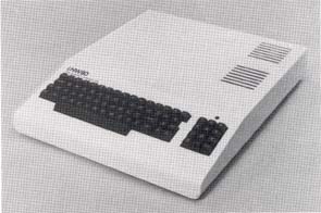
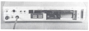
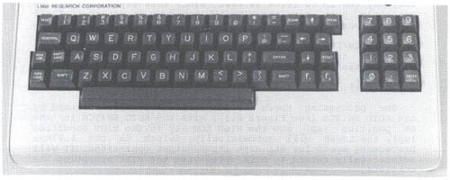
Figure 2.1 - 3/4 Rear view. Keyboard The LNW80 keyboard is pictured in Figure 2.2. The keyboard allows you to interact with the computer. You enter data, programs and control characters by typing on the computer keyboard. The main section of the keyboard is similar to that of a typewriter, with some extra keys which relate strictly to computer functions. To the right of the keyboard is a numeric pad to facilitate data entry in accounting or mathematical applications. Figure 2.2 - Photo of LNW80 Keyboard
RESET - There are two reset keys, one on each side of the main
part of the key board. The RESET keys are used to reset the
computer AFTER it has been initially turned on.
If you don’t have disks, reset the system by holding down
the BREAK key and then pressing both RESET keys
simultaneously. If you have disks, reset the system by
pressing both RESET keys.
ENTER - When you type or enter data into the computer, you
must press the ENTER key to signal the computer that you are
finished with your input. The computer will then process the
data you have entered.
BREAK - This key generates an escape code which is used by the
BASIC interpreter to stop execution of a program. It is also
used in word processing applications and in some system
programs, e.g., DISKZAP, which comes with the DOSPLUS disk
operating system. BREAK will not usually return control to you
when the system 'hangs.' For example, if you try to CLOAD a
program from cassette and it’s not set up correctly, the
system hangs. It will now ignore your incessant pounding on
the BREAK key until you either hook-up the cassette recorder
correctly or RESET the system.
CONTROL - This key is used to generate special codes when used
with another key. It is especially useful in data
communications and word processing.
HIGH/LOW - Ordinarily the LNW80 Computer runs at a clock speed
of 4MHz (4 million cycles per second). Certain input/output
(I/0) situations may require a slower processing cycle, in
which case, this key may be pressed to give a clock speed of
1.77MHz.
The 4MHz speed is over twice the speed of the TRS80 Model
I. When programs written for the Model I are run on the LNW80,
they may run up to twice as fast. Since this may not always be
desirable, just press the HIGH/LOW key down to return to TRS80
model I speed.
The HIGH/LOW key also serves to select the data transfer
rate for the cassette interface. When the H/L key is in the
HIGH position, data as SAVERS or LOADed at 1000 baud. With the
key down, data transfer is at 500 baud (TRS80 model I
compatible).
The processing speed of the computer is also affected by
the AUTO SWITCH (see Figure 2.3) . With the AUTO SWITCH in the
ON position (up) and the HIGH LOW key in the HIGH condition
(up), the LNW80 will automatically switch to the 1.77MHz
processing speed for ALL disk input/output operations. It will
automatically return to HIGH speed when the disk operation is
complete.
This allows programs written on TRSDOS 2.1 & 2.3 (as well
as NEWDOS 2.1 and operating systems listed in Section 11,
Table 11.0 which have a NO in the '4MHz OK' column) to operate
at the high CPU speed except for disk I/0. If these operating
systems are run at 4MHz during disk I/0, a "DISK ERROR"
message will be displayed.
Note: NEWDOS80 2.0 will run at 1.77MHz all the time if the
AUTO SWITCH is ON (up).
RIGHT ARROW - Tab key. Tabs 8 spaces to the right.
LEFT ARROW - Backspace one position and delete.
CLEAR - Clears screen, homes cursor, switches to 64 characters
per line.
Fl and F2 - The Fl key generates a down arrow. The F2
generates a right arrow. Disk operators use
SECTION 3: VIDEO DISPLAY
Introduction
You will require a video display unit (VDU or monitor) to
operate your LNW80 Computer (The video display is sometimes
called a CRT or Cathode Ray Tube). Your selection of VDU will
no doubt depend on what you want from your computer.
If color graphics is your bag, then a color monitor of some
sort is required. An ordinary color TV (NTSC) will suffice,
but there are some limitations when using a TV set as a
monitor. The resolution of a TV set is not sufficient for the
display of text unless the display is set for a screen width
of 32 characters. Also, you will need to attach an R/F
modulator between your LNW80 and the TV set. TV sets aren’t
very good monitors, and because of the low resolution,
graphics displays are rather fuzzy.
An NSTC color monitor, with composite video input, will
provide good color graphics and text an 32 characters per line
mode.
An RGB (Red Green Blue) color monitor will provide
excellent resolution for graphics and text.
See Appendix A, "A Buyer's Guide to Monitors".
Connecting a Monitor
Set the monitor on top of the computer and locate the three
monitor jacks on the I/0 panel at rear (see Figure 3.1).
Notice there are separate jacks for B/W, color TV with RF
modulator or color monitor, and RGB monitors. Attach your
monitor with the appropriate cable. The B/W and color TV
cables are standard computer-to-monitor connector cables.
Connecting an RGB Monitor
The RGB monitor has a separate gun for each of the three
colors red, green and blue. Each gun requires a distinct
signal, and hence, the computer-to-monitor cable is a little
more sophisticated. You will notice that the RGB jack is a
six-pin DIN type female connector. A mating connector for this
jack is provided; however, you will have to provide the cable
and connector for the RGB monitor. Below are the pin
specifications for the monitor and RGB connectors:
LNW80 RGB Connector Signal Monitor Connector
Pin 1 Vertical Sync Pin 8
Pin 2 Blue Pin 4
Pin 3 Green Pin 3
Pin 4 Red Pin 2
Pin 5 Horizontal Sync Pin 7
Pin 6 Ground Pin 5,6
The RGB interface is shown below with pin numbering.
Figure 3.1 - LNW80 RGB Monitor Jack
Figure 3.2 - LNW80 Video Display
Note: For "First Time Through The Manual" People . . .
If this is your first time reading through the manual,
please move on to the next section at this point. When you
have made your way through Section 6, entitled "Power On," the
rest of this section will make more sense.
Using the Monitor with BASIC
Cursor
After performing an operation, BASIC announces its return
to the immediate mode as follows:
READY
>_
( ">" = PROMPT, "_" = CURSOR )
The cursor may be moved along the line by the space bar or
the right arrow, which tabs eight spaces to the right.
Scrolling
When the cursor is positioned on the bottom line of the
display and ,you depress the ENTER key, another line is added
to the display. At the same time, all the lines currently
displayed move upwards, and the line at the top is erased.
Inverse Video
Inverse video can be generated by the following program.
You may have to brighten the screen to observe the effect.
(Results can vary with different monitor types).
10 A=INP (254)
20 A=A OR 1
30 OUT 254,A
Inverse video is only good for black and white. It is not
defined for color.
Text Characters
The BASIC program below displays the text characters
together with their ASCII codes that are available from the
character generator.
10 '......TEXT GENERATOR
15 CLS: X=0
20 FOR K=32 TO 127
30 PRINT @ (X),Z; CHR$(Z)
40 LET X=X+8
50 NEXT Z
You may alter the text and graphics characters by using the
CHARM program, which is available from your dealer.
Graphics Characters
The low-resolution graphics characters available from the
character generator and their accompanying ASCII codes are
displayed by this next program.
10 ’.....GRAPHICS GENERATOR
20 CLS: X=0: Y=0
30 FOR Z=128 TO 191
40 PRINT @ (X),Z; CHR$(Z)
50 LET X=X+8: LET Y=Y+1
60 IF Y/8=INT(Y/8) THEN X=X+64
70 NEXT
80 GOTO 80
The phone plugs are connected to the cassette player by
color code as follows:
GREY - connects to the AUXillary input
SMALL GREY - connects MIC REMote control
BLACK - connects to the EAR phone input
The AUX line carries information from the computer to the
cassette tape.
The EAR line carries information in the other direction,
from the cassette to the computer.
The MIC REM line carries a signal from the computer which
controls the motor in the cassette player.
Using a Cassette Recorder
A cassette player provides a handy, low-cost method of
loading and storing programs. If this is your first computer,
experiment to get familiar with cassette player operation
before storing any close-to-your-heart programs. Before
playing with the cassette recorder, it would be a good idea to
clean the tape heads and the rubber pinch roller with
isopropyl alcohol. An alcohol swab after every few hours of
use, will keep the heads and roller clean. So called "cleaning
tapes" are not recommended, as their abrasive action may
damage the heads. Cheap tapes are not recommended.
Transfer Speed
Programs and data can be transferred to and from the tape
surface at two different transfer speeds. The faster transfer
rate is 1000 bits per second (baud), and the slower rate is
500 baud. By using the
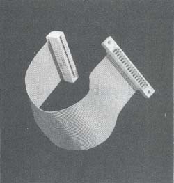
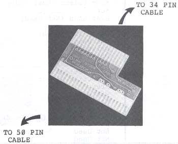
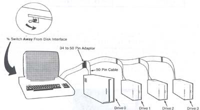
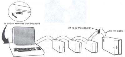
Connecting an 8" Disk Drive
Eight-inch drives require 50 - wire ribbon cables for
operation, You will notice that the disk interface on the
computer is made for a 34-wire cable (17 connections on each
side). A 50-to-34 adapter board is available from LNW (stock#
1096) to connect the 8" drive to the 34-wire cable. One end of
this board plugs into the 8" drive cable-connector (50-pin),
the other into the 5-1/4" drive cable-connector (34-pin) as
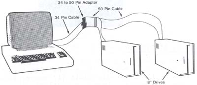
shown in Figure 5.1. If the connector on the 34-pin cable has
pins pulled, you may only connect one 8" drive per adapter.
Otherwise, the drive select process will not be able to "see"
any 8" drive after the first one it encounters. If the cable
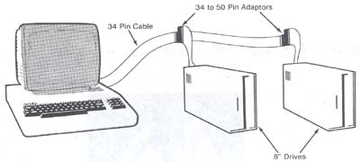
is not of the pulled pin type, then you may connect a few 8"
drives to the 34-pin cable using just one adapter. Figures 5.2
and 5.3 outline the rights and wrongs of the matter.
Figure 5.1 - 34 to 50 Pin Adapter
Figure 5.2 - Pulled pin cable and 8" drive
Figure 5.3 - No pins pulled cable and 8" drive hook-up.
Table 5.1 - Pin Specifications for the 50-pin 8-inch Drive Bus
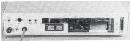
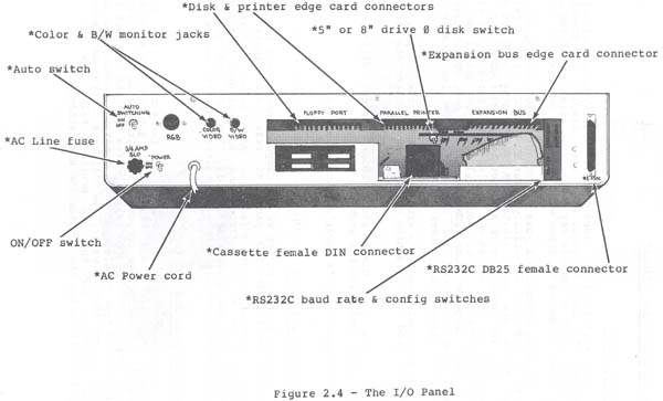
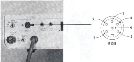
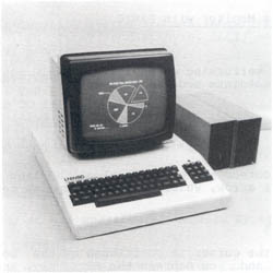
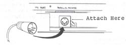
Figure 5.0 - Extender Cable
Pin # Description 2 Not Used
4 Not Used
6 Not Used
8 Index
10 Drive Select 1
12 Drive Select 2
14 Drive Select 3
16 Motor On
18 Direction Select
20 Step
22 Write Data
24 Write Gate
26 Track 0
28 Write Protect (Active Low)
30 Read Data
32 Side Select (Dual Sided Drives)
34 Not Used