This is a translation to english of the pages 217 to 221 of the book "Die Rechenmachinen von Konrad Zuse" by R. Rojas (editor)
(translator notes:
Konrad Zuse*
Zuse K.G., Neukirchen (Kr. Hünfeld)
The period from May 8th, 1945 up to and including May 7th, 1950 is not included in the patent period (Ges. v. 15.7.51
Patent application announced on 18th September, 1952
Patent distribution announced on 18th February, 1954
It is known that calculators can be constructed from only electrical relays as working elements (for example Patent registration 458 481). This fact finds its logical reason from the fact that all calculation operations can be constructed from the basic operations of conjunction (A + B), disjunction (A ∨ B) and negation (/A). The conjunction is realized by serialize contacts, the disjunction by connecting contacts in parallel. The negation is realized by utilizing the rest contact, where the contacts are switched with electro-magnets controlled by the signals (A, B). The resulting value (in the sense of Propositional calculus) create new signals which can be combined, using the basic operations, until the final result is reached. The single operations create signals which are two-way variable (Yes-No-values). Because of this is the method is specially suited for calculations in the 'sekundal-system', as this already uses the numbers 0 and 1.
In contrast to this invention there are working elements which reproduce the functions of the electrical relay in a mechanical way. Elementary working elements for calculators should be developed which solve the basic logical operations, allowing the construction of calculating circuits. The invention does not cover all these circuits.
An electrical relay represents a controllable switch, where the controlling pole works on two cunductors by using an electro magnet. Mechanical plates replace de conductors .... moveable stacked plates, having cutouts which allow moving pins. Controlling plates set the position of pins, allowing plates to be connected or disconnected.
* The images and remarks to the diagrams are from Götz Widiger.
208 Konrad Zuse
Mechanical switching element 209
The images one to seven show examples of mechanical switching elements:
There are three types of plates:
By duplicating and arranging plates so they become symetrical to the center, the operation is improved.
Image 2 shows the basic mechanical switching element, a is the moving plate, b the moved plate, c the control plate and d a guidance plate. a and b can be moved along the X-axis and have cutouts for a pin, connecting the two plates. The pin can be placed in the active and basic position by the Y-axis oriented plate c. The cutout in plate a and b is shaped so the plates are conencted only in the active position. The control plate (c) has a obong shaped cutout, so the pin is limited only along the Y-axis. Along the X-axis the pin can perform the active cycle. The base plate d has an L-shaped cutout, which allows movement of the pin in the active phase, but fixes it in the basic phase. The opation is as follows: The plates a and b are in the staring position, The control plate (c) is placed in the desired position. Then the plate a is moved to the right; depending on the position of plate c, plate b is caried forward or not.
Image 3 shows a similar switching element, with the purpose of of connecting plate a with plate b in one position of the control plate and with plate cin the other position.
These switching elements are used for solving the problem of the actual calculations. In calculating machines, another problem occurs, namely the storage of values, mainly numbers, so they can be used later. Because only the elementary parts are developed here, it is sufficient to create a storage switching element, which stores an elementary value, which has only two states (a binary value for example). This storage switching element is shown in Images 5, 6 and 7.
210 Konrad Zuse
The plates are only drawn insofar as is needed to understand their operational relations. a is a control and moving plate; it is moved on the Y-axis and works as a control plate from there. In the other case, in the Y-position (see indication level above) it is moveable on the X-axis as a moved plate. b is a moved and a control plate and operates on the X-axis, c is a fixed plate with an U-shaped cutout. In Image 5 the plates are drawn in the base-position. The pin position carries the actual storage information. It is placed in the left or right leg of the U-shaped cutout of plate c, which corresponds to the storage of both options.
Image 6 shows all the mechanical phases of reading from the storage switching element in sequential order, at the left for the left and right for the right placing of the pin. The plate (a) is first moved up (Y-axis), then to the right (X-axis). This results in moving plate c to the right if the pin is in the left position, or plate c is stationary when the pin is in the right position. The stored value is thus transferred to the plate c.
Image 7 shows the cycle of steps during the write cycle, left for a left placed pin, right for the right placed pin. The plate (c) is first moved to the right, making the upper part of the cutout free. Than plate a is moved up (Y-axis). Next the pin is moved by plate b to either the left or right. Finally by moving plate a then plate b, the pin is moved to the base position. Then the pin corresponds with with the position of plate c.
Combining the described switching elements to circuits takes place in such a manner, that they can be placed next to each other. The fixed guiding or base-plates can be constructed out of one plate. The plates connect one switching element to the next; so the moving plate of one switching element can work as the moving or controlling plate of the next element.
Image 4 shows a example of an switching element, at the left as mechanical switching element, at the right as electroc relay circuit. The logical equivalent of both is:
(e + f) OR (/e + /f) = b.
It can control the sign for multiplication and division operations. Equal signs for both factors corresponds to lines respectively plates a and b while connected through c or d, so that b is live respectively the plate moves when plate a is moved. With unequal signs, it follows from the design that plates a and b are not connected.
The mechanical switching elements can be placed easy next to each other and in layers above each other, making allowing great space savings in comparison with electrical relays. Because the circuits are build out of similar elements with repeating plate shapes, constructing mass produced elements using punching techniques becomes easy (outstanding).
Mechanical switching element 211
PATENT CLAIMS (warning this is translated patentese!):
Referenced publications:
German patents No 377 694, 173 397, 443 477;
French patent No 737 538 (German patent No 664 012).
212 Konrad Zuse
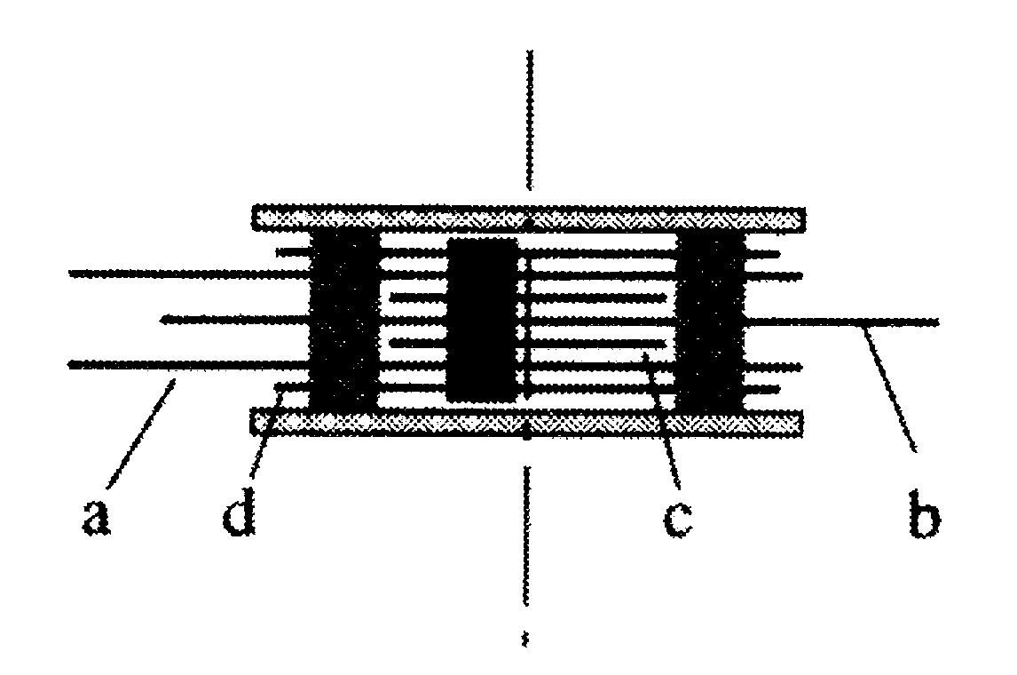
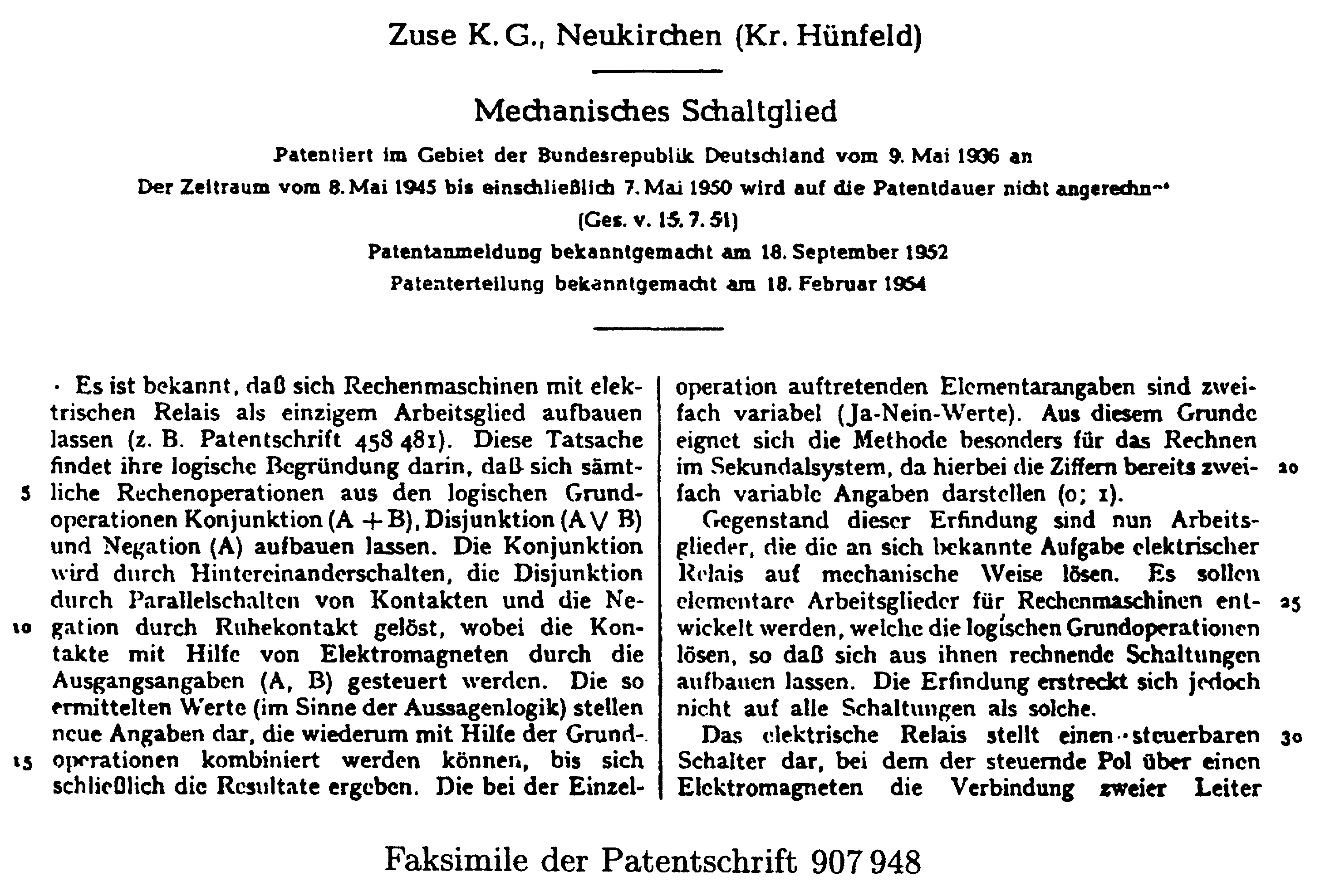
Image 1. Simple switching element (transverse cut)
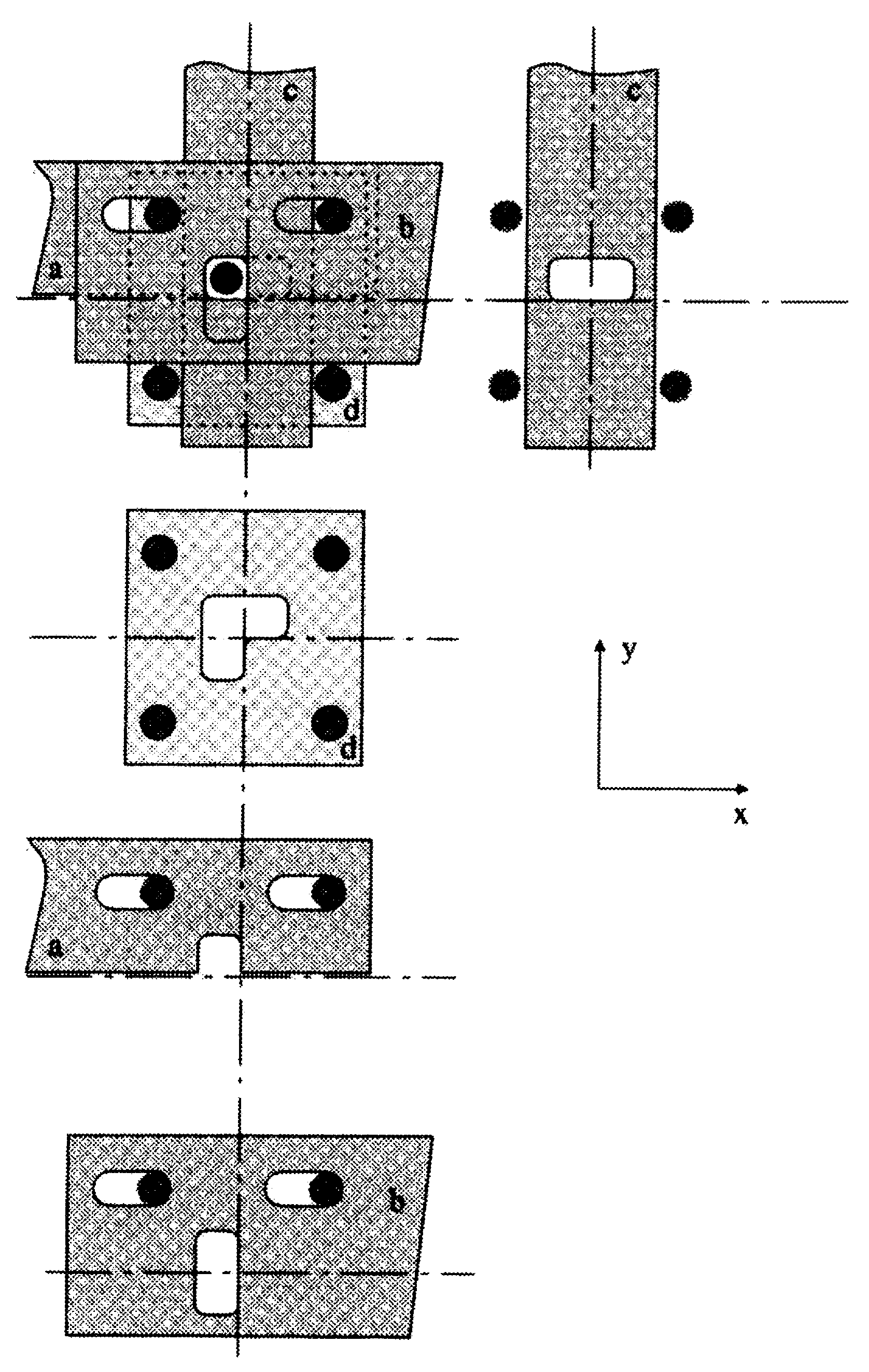
Image 2. Simple switching element
Mechanical switching element 213
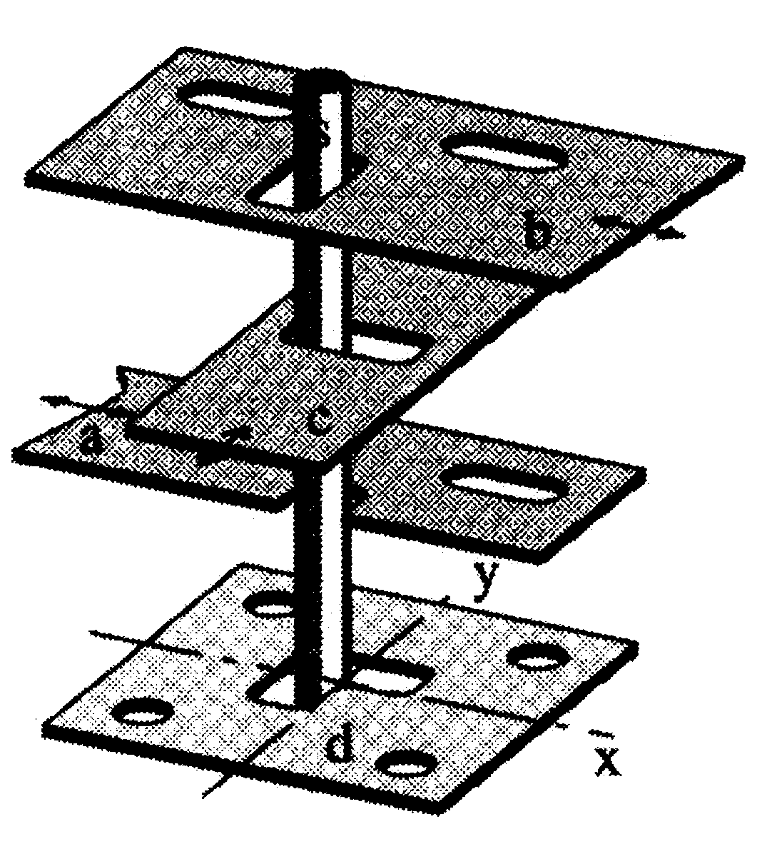
Remarks1. The images 1 and 2 from the patent application show a simple switching element. The cut through drawing shows that some of the plates are applied twice for technical reasons. For the simple switching element these are the plates a, c and d. The top view and three dimensional view show only one plate. The perspective view on the next pages are not part of the patent application, but are added here to gain a better understanding. The clarity is improved and the guidance pins are also omitted. The arrows indicate the possible directions of movement.
The simple switching element has the function of a switch: depending on the position of control plate c the movement of plate a is transferred to plate b. Only when control plate c is placed in the positive Y-position, are the plates a and b connected through the switching pin. Base plate d and the four guidance pins limit the movement of the switchin pin.
a: moving plate
b: moved plate
c: control plate
d: base or fixed plate
s: switching pin
1) All image captions and remarks are from Götz Widiger.
214 Konrad Zuse
Image 3. Variant of the first switching element
Mechanical switching element 215
Remarks. Image 3 shows a variation of the simple switching element. Depending on the position of control plate d, one of the moved plates is coupled to moving plate a through the switching pin. The fixed plate e limits the movements of the switching pin.
a: moving plate
b, c: moved plate
d: control plate
e: base or fixed plate
s: switching pin
216 Konrad Zuse
Image 4 Circuit of the logic equivalent
Mechanical switching element 217
Remarks. Image 4 represents an logically equivalent example circuit. The plates a and b are only coupled through two switching pins and floating plates c and d, if both control plates e and f are in the same vertical position.
a: moving plate
b: moved plate
c, d: floating plate
e, f: control plate
g: base or fixed plate
s1, s2: switching pins
The image in the middle right (opposing page) shows the equivalent relay circuit. This circuit example shows that some plates can simultaneously be moved and moving plates: The floating plates e and f are (assuming they are coupled) moved by plate a and can move plate b. For the plates e and f corresponds the movement in the positive Y-direction an "1" respectively "L". This results in the following circuit table:
| e | f | b |
|---|---|---|
| 0 | 0 | a |
| 0 | L | 0 |
| L | 0 | 0 |
| L | L | a |
218 Konrad Zuse
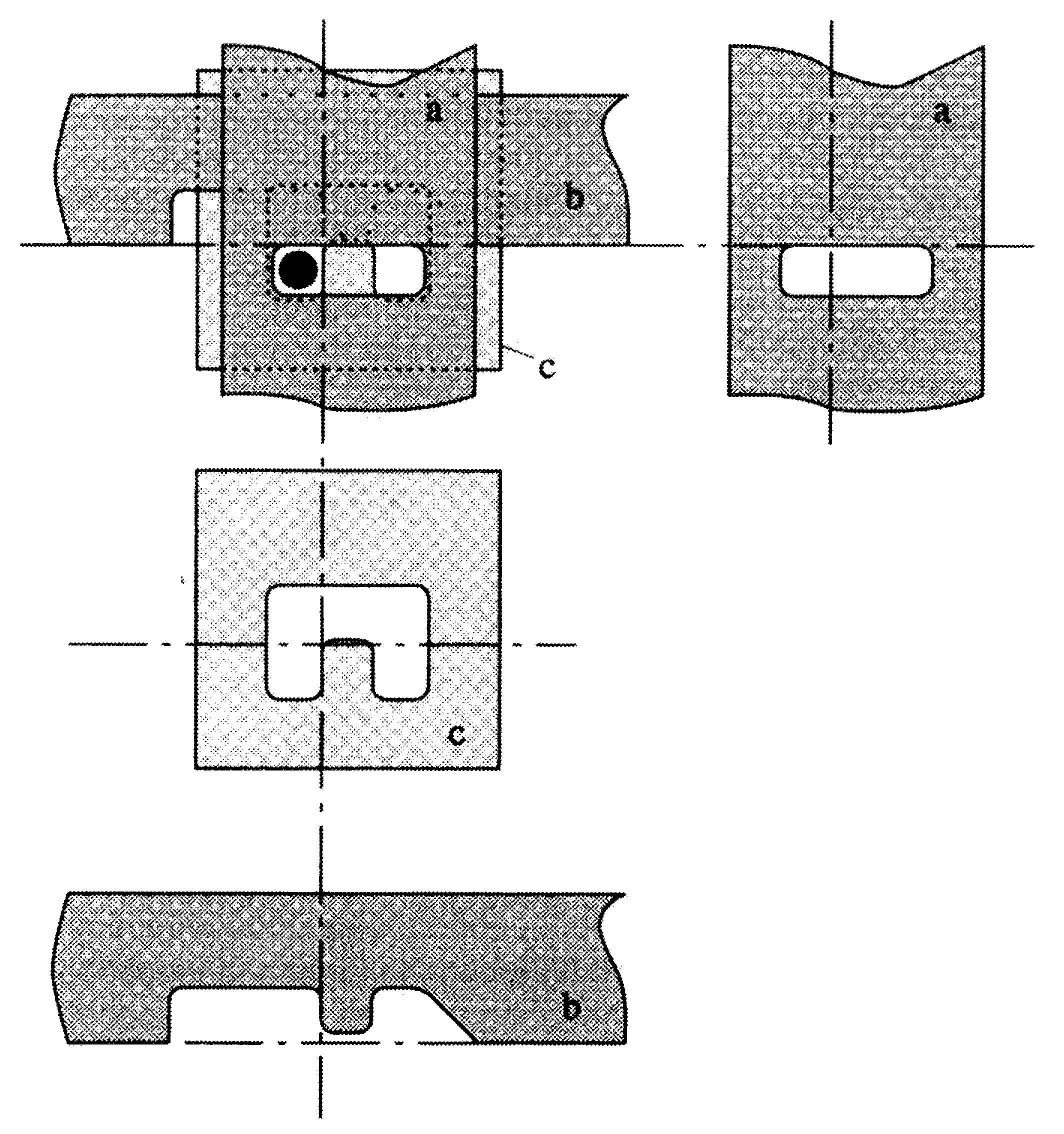
Image 5. Diagram of a storage switching element
a: control resp. moving plate
b: control resp. moved plate
c: base of fixed plate (original says control plate)
s: switching pin
Remarks. Image 5 shows a storage element. It stores one bit. When the switching pin is on the left of the notch in the coutout in plate c, a 1 ("L") is stored. The plates a and b operate, depending on the operation as control, moving or moved plate. The cycle of movements for reading respectively storing are demonstrated by images 6 and 7.
Mechanical switching element 219
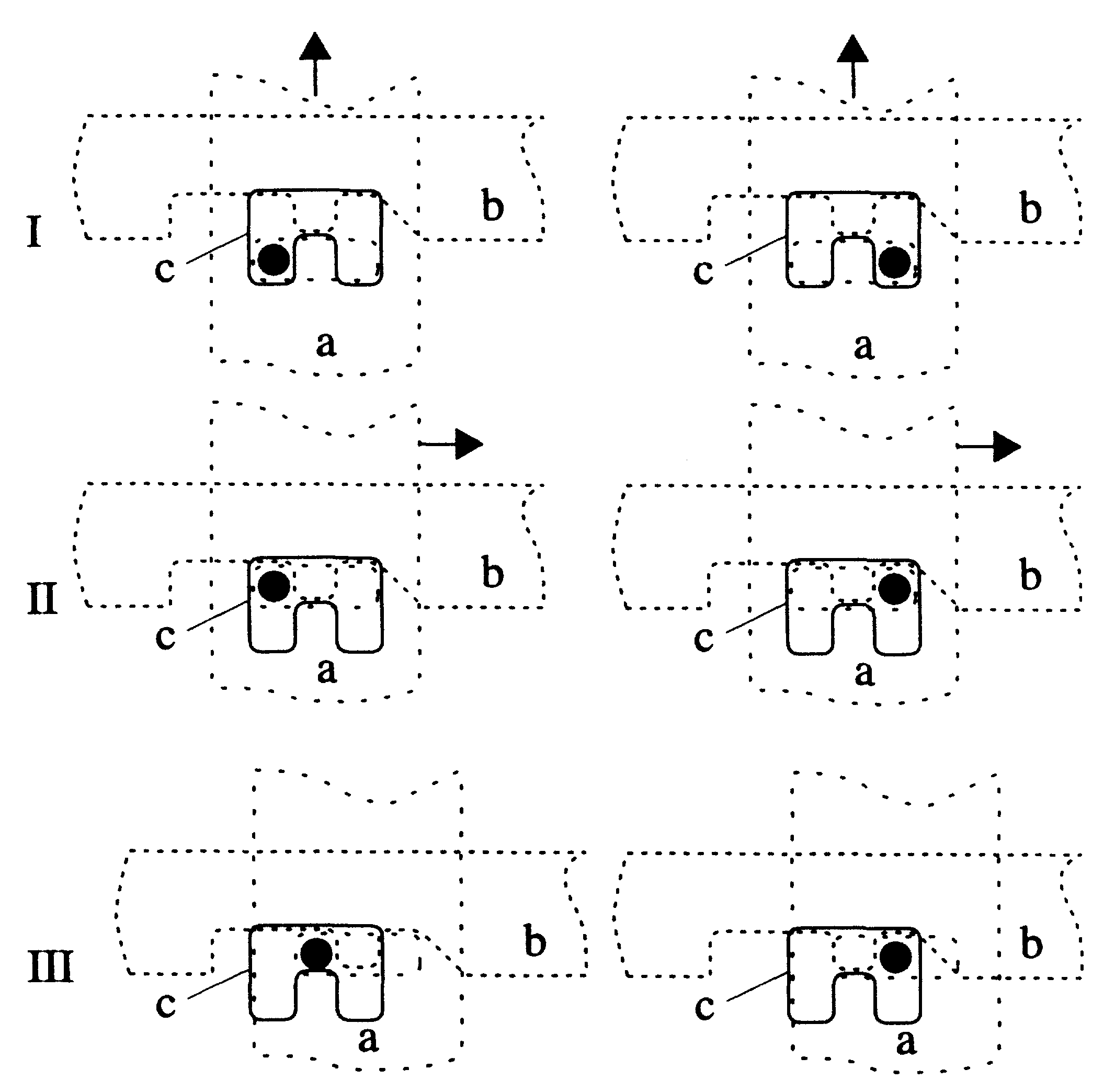
Image 6. movement cycle for reading
Remarks. Image 6 shows the particular positions (I to III) for a reading cycle for two storage elements. The left element stores a "1", the right a "0". From base plate c only the cutout is drawn as solid line. The arrows show the respective direction of movement for the transition from one position to the next.
| I: | Base position. The left side stores a binary 1 ("L"), the right stores a "0". |
| I -> II: | Plate a operates as control plate and moves the switching pin in the positive x-direction. |
| II -> III: | Plate a operates as moving plate (to the right), plate b is moved. When the switching pin is in the left position ("L" stored), it is moved by plate a to the right. The coupling through the switching pin also moved plate b. When however the switching pin is in the right position ("0" stored), the movement of plate a does not move either the switching pin or plate b. |
The other three steps which return the plates to the base position are not shown.
220 Konrad Zuse
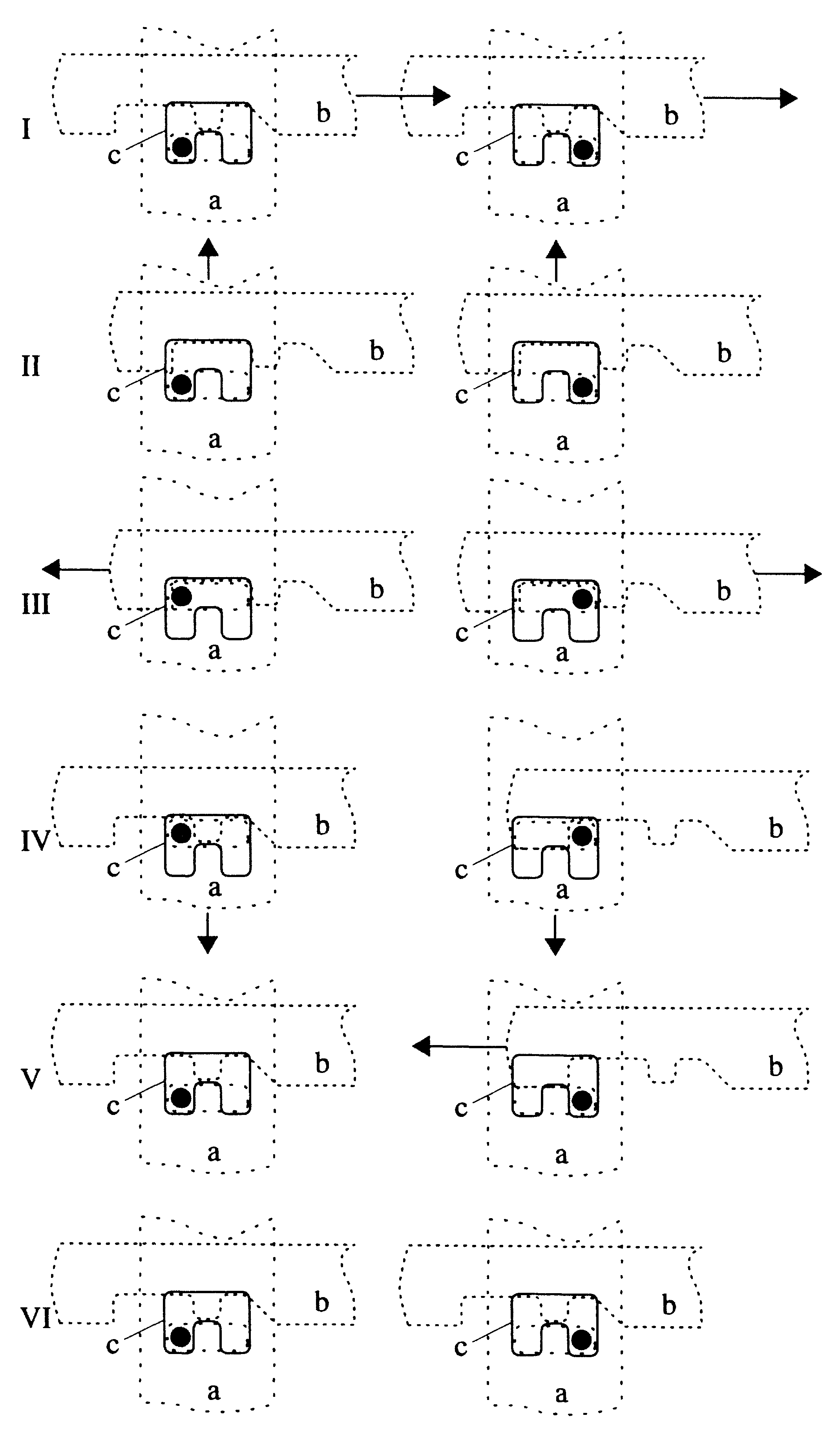
Image 7. Operation cycle during a write operation
Mechanical switching element 221
Remarks. Image 7 shows the positions (I to VI) during a write operation for two storage elements. The left element stores a "1", the right a "0"; in both elements the same value is stored.
| I -> II: | Plate b is moved in the positive X-direction. This makes the upper cutout of plate c accessible. |
| II -> III: | Plate a is moved up and operates as control plate, moving the switching pin in the positive y-direction. |
| III -> IV: | Depending on the value to store (left a "1", right a "0"), plate b is moved to the right or left. In both cases is the switching pin is moved by the notch on plate b. |
| IV -> VI: | The plates a and b are returned to their base position. |