Source: HX-20 Software; Assembler & Disassembler, p. 70 and up
The protocol is a modified subset of CP/NET. The original protocol assumes a simple structure consisting of a computer and a peripherial connected with an asynchronous line. As the Epson variant allows for more pheripherials, the ENQ message is extended with Source and Destination fields.
A typical exchange between a computer (HX-20, PX-8, PX-4) and a peripherial (disk unit or display unit) looks like this:
This has two phases;
The enquiry consists of 5 characters:
The acknowledgement from the Slave is a single character:
Note that only the addressed Responder sends an Ack. Other Responders should stay passive until both devices have signalled the end of an exchange by sending an EOT.
This has three phases;
The function code from Master to Slave contains 7 characters:
The acknowledgment from the Slave is a single character:
The response from the Master:
This has three phases;
The payload from Master to Slave consists of a variable number of characters:
The response from the Slave is a single character:
The response from the Master:
When the Initiator is done the Header and Send Text procedure, the Responder starts its own Header and Send Text procedures
The Responder sends an EOT following the Send Text, which is confirmed by the Initiator with an Ack. The Initiator then sends its own EOT, which is confirmed by the Responder with an Ack.
Then the channel is free for the next message exchange.
Below a edited and annotated dump of a PX-4 “1>” requesting the first directory sector of a floppy drive “>2”. The original dump is produced by this Arduino sketch: https://github.com/electrickery/DualSerialMonitor.
#Serial scope v0.1.0
#Monitoring Serial1 as '1>'
#Monitoring Serial2 as '2>'
1>04 31 31 23 05       # EOT, P1, FD1, PX-4, ENQ
2>06                   # ACK
1>01 00 31 23 0D 00 9E # SOH, FMT, FD1, PX-4, RESET DISK, SIZE, HCS
2>06                   # ACK
1>02 00 03 FB          # STX, 00, ETX, CKS
2>06                   # ACK
1>04
2>01 01 23 31 0D 00 9D # SOH, FMT, PX-4, FD1, RESET DISK, SIZE, HCS
1>06                   # ACK
2>02 00 03 FB          # STX, 00, ETX, CKS
1>06                   # ACK
2>04
1>04
1>04 31 31 23 05       # EOT, P1, FD1, PX-4, ENQ
2>06                   # ACK
1>01 00 31 23 77 02 32 # SOH, FMT, FD1, PX-4, READ SECTOR, SIZE, HCS
2>06                   # ACK
1>02 01 04 01 03 F5    # STX, Drv, Trk, Sec, EOT, CKS
2>06                   # ACK
1>04
2>01 01 23 31 77 80 B3 # SOH, FMT, PX-4, FD1, READ SECTOR, SIZE, HCS
1>06                   # ACK
2>02 00 434F4E54454E54535458540076001C0102000000000000000000000000000000524541444D4520205458540030000703000000000000000000000000000000E5E5E5E5E5E5E5E5E5E5E5E5E5E5E5E5E5E5E5E5E5E5E5E5E5E5E5E5E5E5E5E5E5E5E5E5E5E5E5E5E5E5E5E5E5E5E5E5E5E5E5E5E5E5E5E5E5E5E5E5E5E5E5E5 00 03 90
1>06                   # ACK
2>04
1>04
00h     NUL - Null (Send by PX at startup)
01h     SOH - Start Of Header
02h     STX - Start Of Text
03h     ETX - End Of Text
04h     EOT - End Of Text
05h     ENQ - Enquiry
06h     ACK - (Positive) Acknowledge
10h     WAK - Wait For Acknowledge (officially DLE)
15h     NAK - Negative Acknowledge
CKS -  Text Checksum
Drv -  Disk drive (1 based)
FMT -  Message Format Code
HCS -  Header Checksum
Sec -  Sector
P1  -  Polling/Select function (only Select (00) is supported)
RetCode - Return code
SIZE - Size of following text message
Trk -  Track
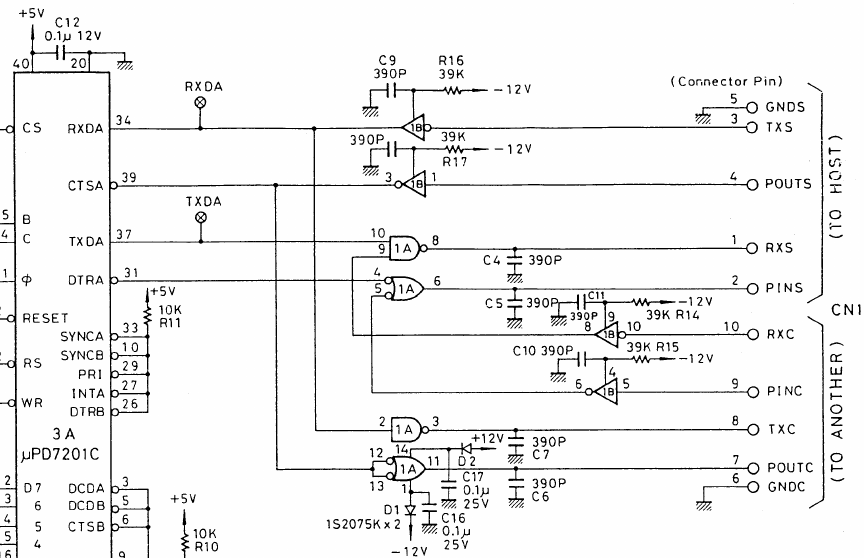
The TF-20 terminal floppy drive implements the network as two serial interfaces using a single UART. Data received on the Host port (HX-20 or PX-4/8) is routed to the Other peripherial port, data from the Other peripherial port is logically ORred with the Peripherial Tx signal. The PIN/POUT circuit using CTS and DTR is not used.

fjkraan@electrickery.nl, 2024-03-31