Having a new multi-channel Logic Analyzer as a new toy, I wanted to try it on the PDP-11 too. The Logic analyzer is this one:
But with previous tests on simple 8-bit systems, and looking how others used this, I found a structured approach whould certainly help to avoid confusion. So this meant making custom cable management systems.
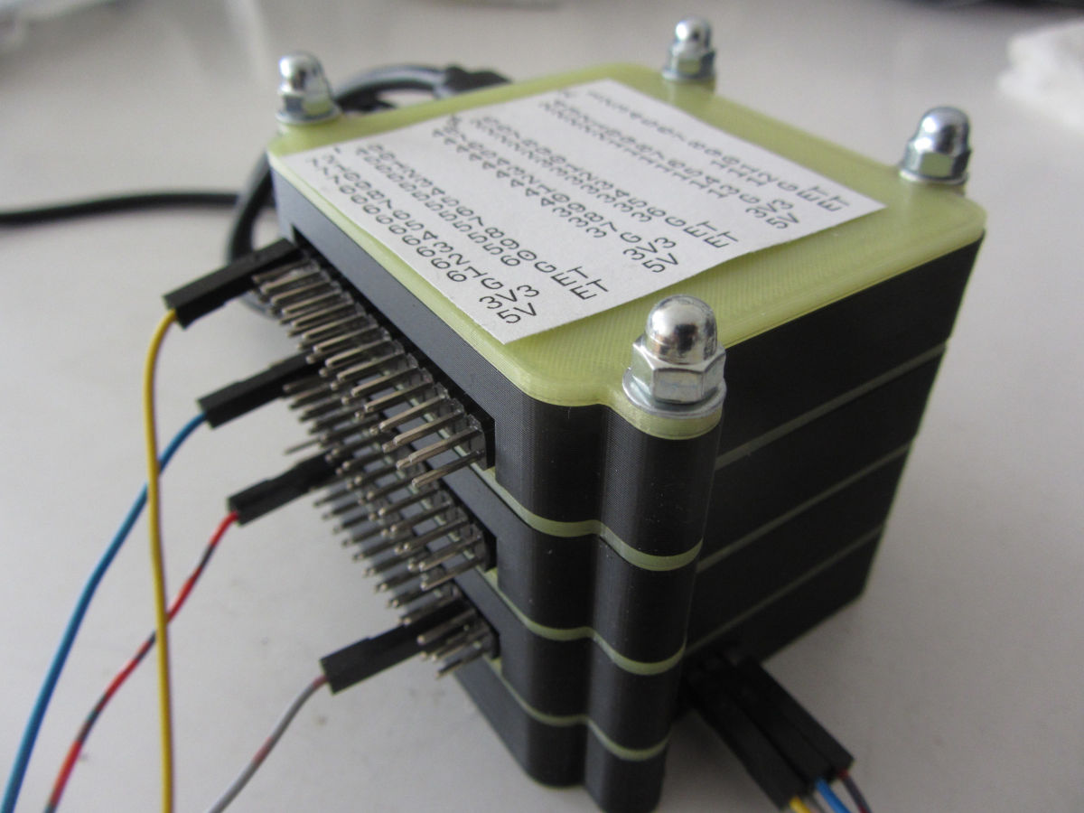
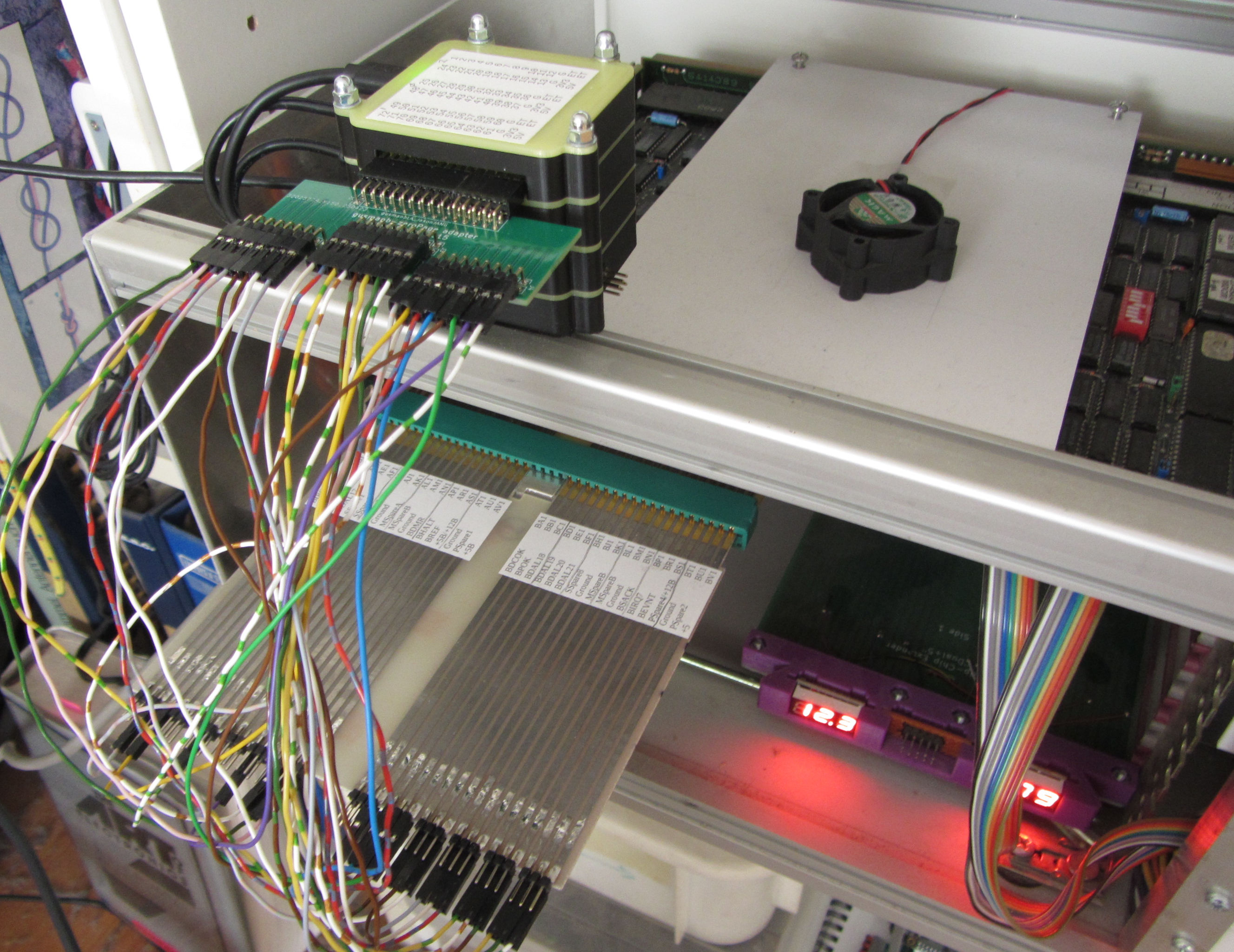
One thing is the connector on the Logic Analyzer. Per board, 24 channels are available. These channels are placed on a two row header, with the middle eight bits wrapping the two rows. Only two ground pins are available. Looking at Joerg's QProbe board and its Zero Plus channel interface, this looked at a much more usable interface. So I came up with this:
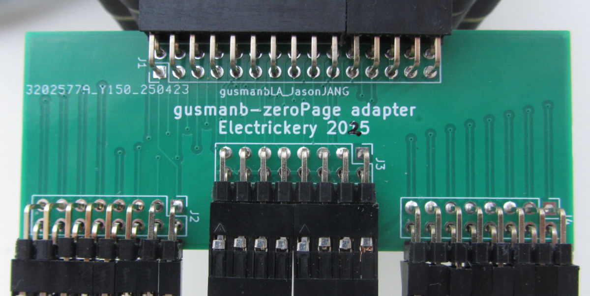
Note the Jason YANG channel header is slightly different from the original. Organizing the 24 channels into three 8-channel pods, makes wiring much more organized. Having extra ground pins is probably a good thing too.
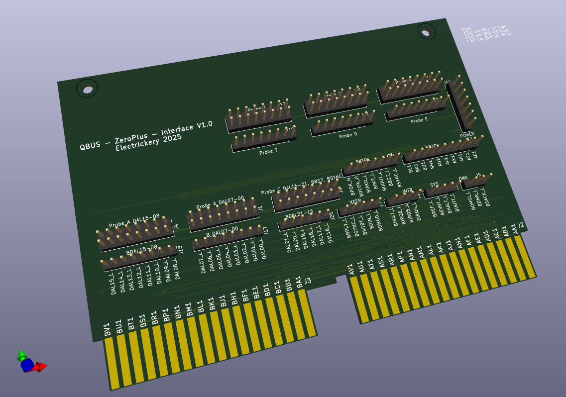
At the other side, the first target to connect is the QBus. Usually other points of interest are usually related to the QBus signals (I assume). Designing a custom QBus board is somewhat more involved, so I made a first naive connector of an unused 'half-extender' board:
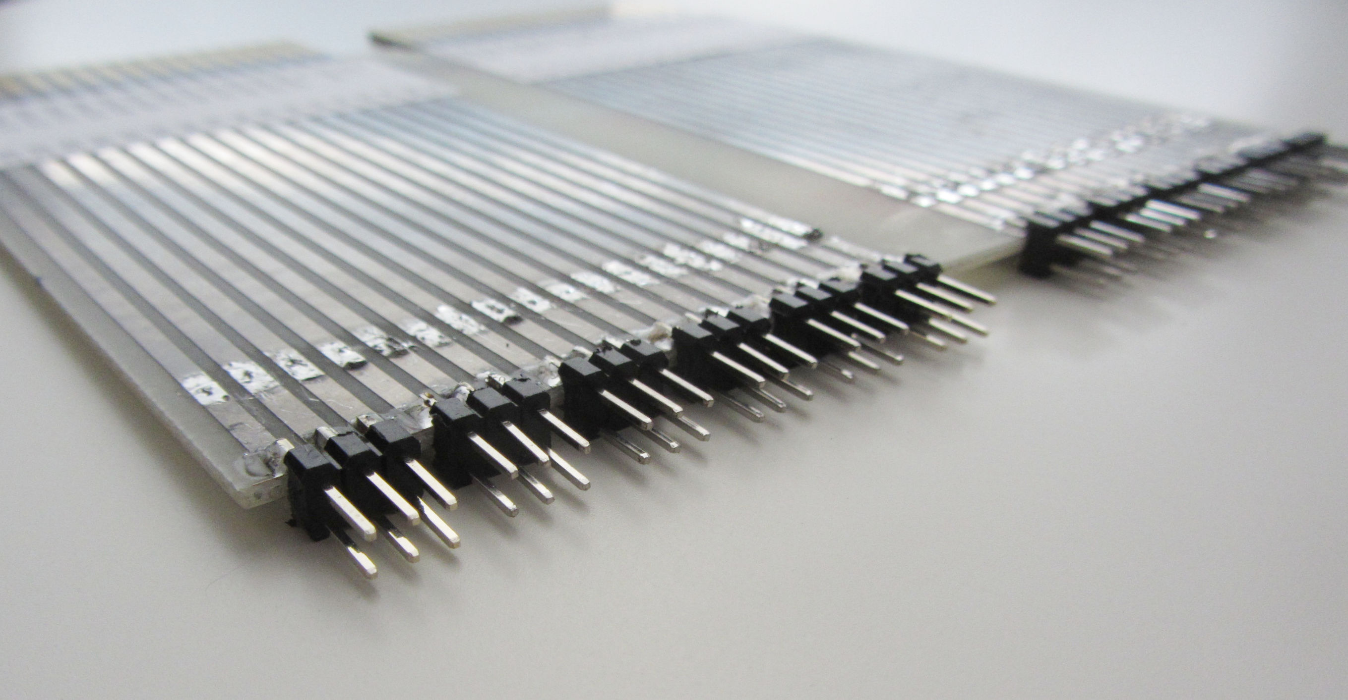
This is not a very robust solution, but good enough for some first testing.
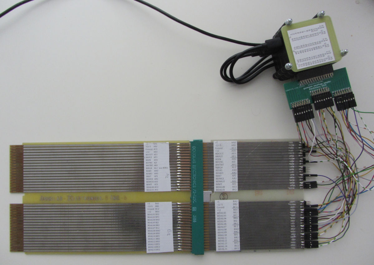
In the setup above, just 24 channels are used: all BDAL signals, BBS7 and BSYNC.
In the rack, only the CPU (M8189), some RAM (M8067) are present. This was good enough to see some signals:
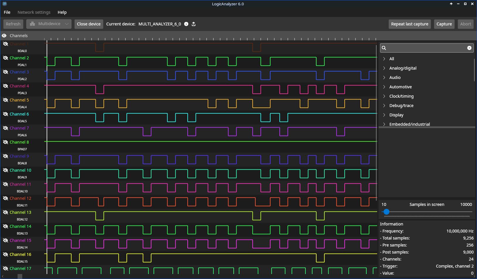
This view is not that simple to interpret, but the software supports decoders, by which sets of signals can be interpreted as data, addressed and cycle phases. Al it needs is some coding in Python.
But up to now, I consider the project a succes, and consider to make a real QBus interface. Integrating level shifters and soldering the R.Pi Pico's on the board is also an option, but more work. With such short lines, termination could be very simple.
Latest update: 2025-05-02