!! Preliminary !!
TECHNICAL CHARACTERISTICS

CPU:	            80C88 (4.77 MHz)

ROM:	            16K bytes

RAM:	            User RAM: 256K bytes, 512K bytes depending on con-
                    figuration.
Video RAM:          16K bytes

CLOCK:	            Battery-backed clock/calender

Minifloppy	    Two 3.5"disk drives.
disk drive:	    Diskettes used:
                    double sided, double density, 135 t.p.i.
No. of heads:       2
No. of cylinders (tracks): 80
Data transfer rate: 250K bits/sec.

Power supply to	    5 V DC (from Power Unit)
Central Unit:	    5 V DC (from battery)

System power	    max. 20 W
consumption:

Display:	    1:2.4 aspect ratio
                    Liquid crystal display (LCD)
                    Alphanumeric:
                    25 lines of 80 characters
                    25 lines of 40 characters (by selection)
                    Graphic:
                    640 x 200 pixels
                    320 x 200 pixels

Keyboard:	    78 keys, including:
                    10 Function keys
                    Numeric keypad (integrated into alphanumeric area)
		    LEDs indicating numeric keypad and upper case mode

Battery:	    Ni-Cd-Battery set, 5 V
                    500 charge/recharge cycles
                    6 hours operation with 10 % use of the disk drives
		    8 hours recharging time

Interfaces:	    Parallel (Centronics)
                    Serial (RS 232C)
                    Interface for the optional 5.25"disk drive
                    Common Bus

31/E


Ambient	Temperature range: from 5 to 35º C (41 to 95º F).
                           conditions
Relative Humidity:  from 20 to 80 per cent, non condensing.
Altitude (max.):    operating 3000 m. (10,000 feet),
                    non-operating 10,000 m. (33,000 feet)

Dimensions/	    385 x 276 x 72 mm.
Weight:	            (15.15 x 10.8 x 2.83 inches)
                    5,700 Kg (12.5 Ibs).

AC Adapter:	    Input: AC (voltage, frequency according to the label on the
                    AC-Adapter)
Output:             5 V DC for battery charging,
                    5 V DC to system
                    AC supply current variations tolerated:
                    Voltage +/-10 per cent
                    Frequency +/-1 per cent

32/E	Installation and Operations Guide
Both the DC and Charge connector
are barrel type. Pin is plus, barrel is minus. DC is 5 Volt, Charge is
some current limited 12 Volt source.
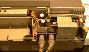
The 5 Volt power supply is internally converted to +/- 12 Volt,
probably for the RS232C port only. The conversion takes place at the
shielded conversion board at the top left, connected to the yellow and
orange wires. |
|
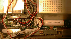
A topview of the back of the
M15. Top left and right are floppy drives. The seven white-wire
connector is CN10, the power connector. The white wires come from the
shielded conversion board.
|
|
|
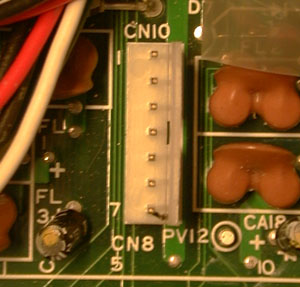
The power connectior is CN10. The pinout is:
1. + 5 Volt
2. + 5 Volt
3. GND
4. GND
5. +12 Volt
6. -12 Volt
7. GND?
|
|
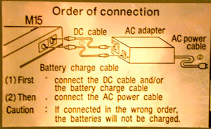
The power supply warns for wrong
connection. IMHO with the wrong connection sequence, the computer won't
start up at all. I don't know about batttery charging, as I haven't got
a battery.
|
|
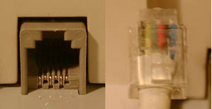
The keyboard uses a 6-pole RJ-11
phone connector. Wire color from left to right; black (GND), yellow,
green (sig), red (sig), black, blue (+5V). Data and clock are on green
and red. Make sure you test this with a PC (XT) keyboard as AT keyboards
are not compatible.
|
|
Back to index
Last update: 2003-11-27
fjkraan@electrickery.nl