1. INTRODUCTION NOTATION The following convention has been used throughout this manual to avoid confusion: 1. Words typed in upper case letters represent commands or instruc- tions to the computer and should be entered in the format indi- cated although not necessarily in upper case since the M10 con- verts all letters to upper case except in TEXT e.g: PRINT TIME$ may be entered as print time$ or PrinT tIMe$ but not PRINT TIME $ where the spacing has been changed. Likewise, symbols have a precise function and must be entered as shown. A list of all symbols used in BASIC programming language appears at the beginning of Part 2 of this manual. 2. Words which appear in lower case print are variables and the user must supply the actual value e.g. PRINT filename In this example, PRINT represents an instruction to be entered as it is, while the user must type the actual name of the file to be printed. 3. The following list shows the meaning of certain groups of words and symbols. A]B]C choose one of A, B or C [ ] items enclosed in square brackets are optional ... three leader dots indicate that more values can be included in the string e.g. DATA constant-1 ,constant-2 ...,constant-n <KEY> the key whose name appears in angle brackets should be pushed e.g. <ENTER> means "press ENTER" M10 Operations Guide 1-1
<CTRL> + x means "press x while CONTROL is being held down" <GRPH + SHIFT> means "press GRPH and SHIFT together" 4. Text appearing exactly as it on the screen is shown in boldface e.g. File to edit? GENERAL DESCRIPTION The M10 is a self-contained, easy-to-use ,personal computer which is fully portable. It is depicted in Figure 1-1 below. It comes in two models, one with integrated modem (M10 MODEM) and one without. In this manual, wherever a reference is made to the M10, it can be assumed that this applies equally to both models. Where differences occur, these are specifically mentioned.
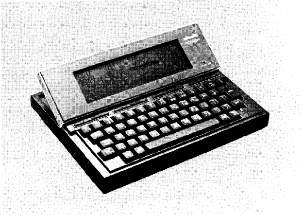 Fig. 1-1 The M10 Portable Computer
The M10 is ideally adapted to many applications. It offers facilities for
programming, word processing, telecommunications, maintaining an elec-
tronic address book and schedule of activities.
The M10 can be operated either from its own battery supply (four 1.5V dry
cells) or from the AC mains supply, using an AC adaptor. It weighs only
1-2
1900 grammes (4 lb 3 oz.), with overall dimensions of 30 x 22 x 6 cm. (11 3/4 x 8 1/2 x 2 3/8 in.) and fits easily into a normal briefcase, making it ideal for use during travel or in the field, as well as in the office or at home. The M10 comes in its own attractive soft case, pro- tecting it from damage and dust. A prominent feature of the M10 is its keyboard and screen. One of the most frequently expressed criticisas of portable computers is that the keyboard is not easy to operate or that the display is difficult to read. This is not a criticism we expect to hear levelled at the M10 with its solid, full-size keyboard and liquid crystal display of 8 rows of 40 characters. TECHNICAL DESCRIPTION The M10 is equipped with 32k of ROM (read-only memory) which accommodates the five built-in facilities. These are: - BASIC interpreter which allows you to create, store and run proqrams. - TEXT for composing text and word processing. - TELCON for telecommunications. - ADDRSS to set up and maintain an electronic address and telephone book. - SCHEDL to keep an easily accessed schedule of your appointments and other activities. The other main features are: - 8k of random access memory (RAM), expandable in 8k steps up to 32k. - OKI 80C85 CMOS microprocessor, compatible with the Intel 8085. - Keyboard giving 188 alphanumeric and graphic characters; the M10 MODEM has a standard USA-ASCII keyboard while Italian, French, German and UK standard keyboards are available for the model without integrated modem. - Additional function keys for special applications. - Tiltable liquid crystal display (LCD), with adjustable screen con- trast. - Interfaces for peripherals. The M10 has three directories in RAM. Filenames are suffixed according to the directory in which they are located. Files suffixed .BA are BASIC language programs stored in binary form. M10 Operations Guide 1-3
Files suffixed .CO are machine language programs. Files suffixed .DO are those created under the TEXT application program or BASIC programs stored in ASCII format or basic data files (this manual deals only with .DO files created under TEXT). INTERFACES AND PERIPHERALS The M10 has interfaces for connecting a variety of peripherals. Note that the M10 MODEM can be connected directly to a telephone for telecom- munications applications whereas the other model requires an external modem/acoustic coupler for this. Figure 1-2 shows a typical configura- tion of the M10 with peripherals attached. Special cables are available for all interfaces.
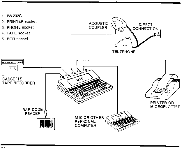 Fig. 1-2 Typical System Configuration
The principal peripherals are:
Cassette Tape Recorder
The M10 can be connected to any model of cassette tape recorder provided
it has, in addition to the standard controls, an input jack (MlC), an
output jack (EAR), a remote control jack (REM) and a tape counter. See
Chapter 9 for further details.
1-4
Printer Any printer or microplotter conforming to the industry standard for parallel interfaces can be connected to the M10 by means of the Olivetti microplotter cable. Telephone The M10 MODEM is equipped with an internal modem which allows it to be connected either directly or via an acoustic coupler to a telephone line. The other model requires an extecnal modem/acoustic coupler. Bar Code Reader The M10 has an interface for connecting a Hewlett-Packard HEDS-3050 or HEDS-3000 bar code reader for stock control applications. The M10 can be connected through the RS-232C interface to another com- puter either directly in local connection or through a modem for remote connection to a host computer system. THE KEYBOARD AND SCREEN The M10 MODEM has a USA-ASCII standard keyboard (see Figure 1-3). The model without integrated modem is equipped with one of four national standard keyboards – Italian, French, German or UK (see Figure 1-4). All of these give the standard alphanumeric character set.
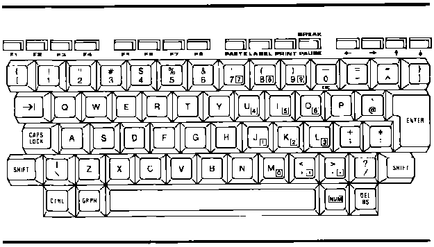 Fig. 1-3 USA-ASCII Keyboard
In addition, by pcessing the key <GRPH>, another 47 characters are avail-
able, as shown in Figure 1-5. Pressing <GRPH + SHIFT> gives a further 47
characters, as shown in Figure 1-6. The character sets given by <GRPH>
810 Operations Guide 1-5
and >GRPH + SHIFT> are identical for all models.
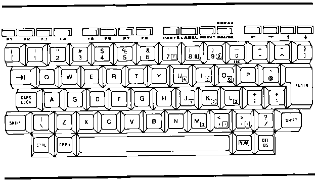 Fig. 1-4 UK Keyboard
Note that all character keys have a repetitive function when held down,
as does DEL/BS, the tabulation key ( mi) and the cursor movement keys.
The SHIFT key has the same role as on a normal typewriter - it changes
letters to upper case and gives the upper alternative on number and sym-
bol keys.
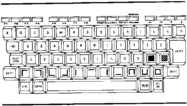 Fig. 1-5 Keyboard When <GRPH> is Pushed
1-6
There is a functional difference between CAPS LOCK on the US keyboard and SHIFT LOCK on the other models. CAPS LOCK acts only on the letter keys, leaving the number and symbol keys unchanged. SHIFT LOCK gives the upper case alternative on all keys. Both CAPS LOCK and SHIFT LOCK remain in position until released by pressing attain. The tabulation key is labelled
 and moves the cursor from one tab to
the next. These tabs are set every eight character spaces and can not be
altered.
CTRL is a key for communicatina special control characters to the com-
puter. 1t is also used in conjunction with the keyboard for certain
functions. These are dealt with as they occur.
GRPH gives access to another character set, as already described.
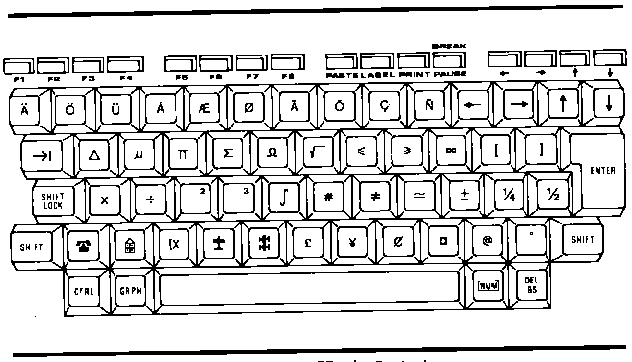 Fig. 1-6 Keyboard When <GRPH + SHIFT> is Pushed
At the right side of the keyboard are 12 keys which, in addition to their
normal characters, carry the digits 0 - 9, a comma and a full stop,
inscribed in a small square as shown in Figure 1-7. This number pad is
accessed by pressing NUN. All other keys are disabled when this is
pressed and remain so until NUM is pressed aaain. 1f your keyboard
apparently blocks, producing no letters but only numbers, you will find
that the NUM key has been pressed.
M10 Operations Guide 1-7
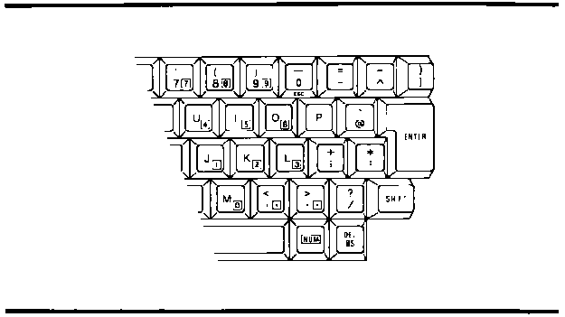 Fig. 1-7 Number Pad on the M10 Keyboard
DEL/BS is the delete/backspace key. Pressing this key deletes the char-
acter preceding the cursor and moves the cursor back one space. In TEXT
mode, <DEL/BS + SHIFT> deletes the character over which the cursor is
positioned and moves subsequent text back one space.
The ENTER key is used to select a program or file from the main menu once
the cursor has been positioned, or to select an option inside one of the
five built-in application programs. It also serves to indicate the end
of a data record in a file and as the carriage return of the display.
Located just below the display are four groups of four keys, labelled in
blue.
The first two groups, labelled F1-F8 are function keys which have dif-
ferent functions, according to the operation being carried out. These
functions are described in subsequent chapters.
The third group comprises the command keys PASTE, LABEL, PRINT and
PAUSE/BREAK respectively. The function of these keys does not vary from
one program to another.
- PASTE is used in 'Cut and Paste' and ’Copy' operations. This is a
text-editing function and has its most obvious application in TEXT
mode. A detailed description of how to use this facility is given in
Chapter 5.
- LABEL is used to display at the foot of the sceeen the function of
F1-F8 for whichever of the five application programs is currently in
use. Pressing LABEL a second time cemoves these definitions from the
screen.
- PRINT is used when a printer is connected to the M10. Pressing this
key causes the current LCD display to be printed. <SHIFT + PRINT>
1-8
prints the entire file and allows the user to specify the number of characters per line to be printed. - PAUSE/BREAK has two functions. In BASIC, the lower case alternative, PAUSE, causes the execution of a program to be suspended. Operation is resumed when this key is pressed again. The upper case alterna- tive,
| KEY | CURSOR MOVEMENT |
 | One space to the right |
<SHIFT> |
To beginning of next word |
<CTRL> |
To end of current line |
 | One space to the left |
<SHIFT> +  |
To beginning of last word (or current word) |
<CTRL> +  |
To beginning of current line |
 | One line up |
<SHIFT> + |
To top line of screen |
<CTRL> +  |
To beginning of file |
 | One line down |
<SHIFT> +  |
To bottom line of screen |
<CTRL> +  |
To end of file |
The screen, on which the characters appear as they are typed, is a liquid crystal display (LCD). It is made up of 8 lines each 40 character spaces wide and each character is formed in a 6 x 8 dot matrix. The right hand column is automatically left blank in TEXT mode to preserve the spacing between words on successive lines. The screen can be tilted manually from the horizontal position to an angle of about 30 degrees for optimum viewing. Screen contrast can be adjusted by means of the circular control on the right hand side panel. Up to 8 lines of text can be displayed on the screen at any one time. When viewing in TEXT mode, the screen can be scrolled up or down by using the cursor movement keys. There is automatic word-wrao in this mode so that if a word over-runs the end of a line, it is automatically carried over to the next line to avoid splitting. Although the M10 screen shows only 40 characters on a line, it is possi- ble, when using a printer, to have up to 132 characters per line on the printed output. REAR PANEL CONNECTIONS On the rear panel of the M10 are a number of connectors, as shown in Fig- ure 1-9.
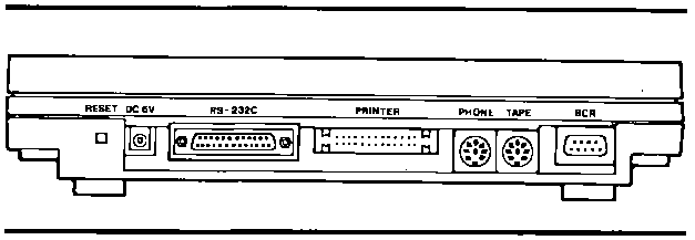 Fig. 1-9 Rear Panel Connections
From left to right these are:
RESET
This recessed button is, as its name implies, for resetting the computer
when it has "frozen" and all functions are blocked. This is unlikely to
happen when using one of the built-in application programs but it could
occur when operating a program of your own devising.
DC 6V
This jack takes the plug on the end of the AC adaptor when the M10 is
connected to the mains supply.
1-10
RS-232C This is an interface conforming to the EIA standard with the exception of the data carrier detect (DCD) line which is not connected. Typical applications of the RS-232C are: - to connect the M10 to an external modem or modem/acoustic coupler. - to connect the M10 to equipment that will act as a data terminal such as the Olivetti ET351 electronic typewriter or the Olivetti PR430 serial printer. - to connect the M10 to another l110 or other personal computer. PRINTER This is the parallel interface output from the M10 to a printer or micro- plotter. PHONE This connection exists only on the M10 MODEM. 1t provides the link between the 810 and a telephone line, either for data communication with a host computer or for automatic dialling of a number (see Chapter 8). TAPE When a cassette tape recorder is being used to store files from the M10 (as is recommended) the recorder is connected to this socket. More is said of this in Chapter 9. BCR This socket provides the connection point between the M10 and a bar code reader. It is specifically designed to connect to the Hewlett-Packard HEDS-3050 or HEDS-3000 bar code reader. This has an application in warehousing and general stock control. M10 Operations Guide 1-11
UNDERSIDE PANEL Underneath, the M10 appears as shown in Figure 1-10.
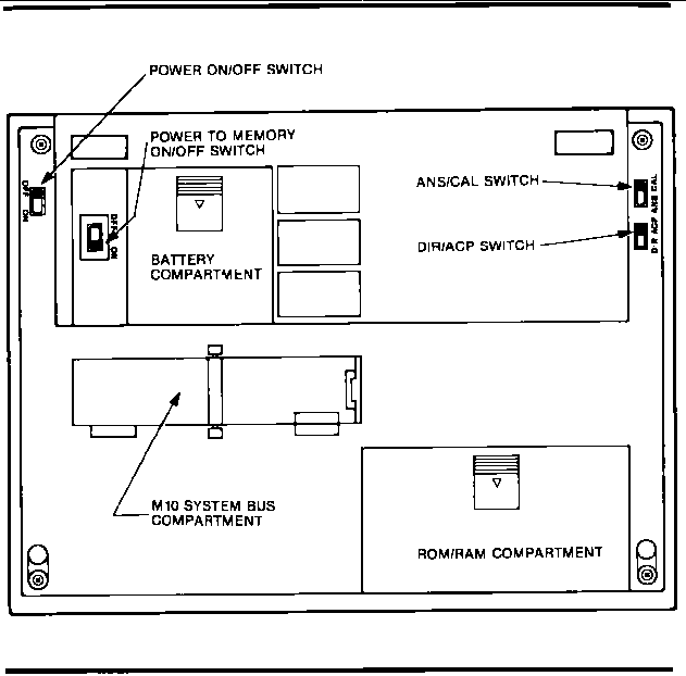 Fig. 1-10 Underside Panel
The features shown in the figure are:
1. Power ON/OFF Switch.
This switches the computer on and off.
1-12
2. Power to Memory ON/OFF Switch This switch keeps power supplied to the memory even when the computer is switched off. When the M10 is delivered, this switch will be turned to OFF. During the start-up procedure, it will be turned to ON and will remain so unless the computer is not to be used for an extended period. It is important to realise that when this switch is turned off, files in storage in the RAN will he lost. All necessary files should be saved on tape before turning the memory power off. The computer will not operate if this switch is off. It is located in a recessed compartment to ensure that it is not turned off by accident. Depending on the amount of RAM installed, the Ni-Cd rechargeable battery supplying the power to the memory will keep the RAM contents intact from between 8 to 30 days when the M10 is switched off. Tt is good practice to make sure the computer is used regularly every few days to keep the battery charqed. 3. Battery Compartment. The M10 is powered by four 1.5V AA alkaline dry cells, installed in this compartment. They should be inserted as shown in Figure 2-1. These ce- lls have an operational life of approximately 20 hours regardless of the memory capacity installed. When the battery is running low, the LED on the front panel marked 'Battery Low' lights up. You then have about 20 minutes of operation left before the battery runs out. Sw- itch off and replace the battery. 4. ANS/CAL Switch (M10 MODEM only). This switch has an application in data communications and is used in the TELCOM program. It is dealt with in Chapter 8. 5. DIR/ACP Switch (M10 MODEM only). The same remarks apply as to the ANS/CAL switch. 6. ROM/RAM Compartment. This compartment contains space for an extension to both the ROM and the RAN. The M10 has 32k bytes of ROM as a standard and this can be increased to 64k with the addition of a single extra block. The standard RAM capacity is 8k bytes which can be extended to 32k in blocks of 8k. M10 Operations Guide 1-13
7. M10 System Bus Compartment. This compartment is closed by a hinged cover and contains a 40-pin con- nection to the M10 system bus. 1-14