LNW80 Microcomputer Operations Manual
SECTION 8: LINE PRINTER INTERFACE
Line Printers
There are two types of line printer:
1. Serial line printer
2. Parallel line printer
You can connect either type to the LNW80 Computer. The
physical connections for each differ from one another, as they
carry data differently.
A serial line printer handles a byte of information by
receiving the basic elements of information (the bits) in
serial fashion, i.e., one after another, or bit-by-bit, like
eight cars following any behind the other on a single-lane
road. On reception of eight bits the printer reconstructs the
appropriate character.
Parallel printers, on the other hand, receive information
byte-by-byte. At any one time, at least 8 bits are travelling
parallel to one another along the ribbon cable, much like 8
cars abreast on an 8-lane freeway.
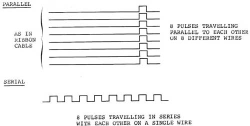
Figure 8.0 - Parallel and Serial Data Flow
Serial Line Printer
Serial line printers must be connected to the RS-232 serial
communications interface. A DB25 socket is required to make
this connection. The transmitting rate must be set on the TX
switch to the right of the interface. You will also, in all
probability, have to modify the the printer line so that it
can interface with the RS-232 interface. Because connection of
a serial printer requires some knowledge of RS-232 operation,
details on tne "how tos" of serial printer connection are
found in Section 9.
If you are currently on the hunt for a printer, do yourself
a favor and make it a parallel one.
Note: In order that the LPRINT and LLIST commands of BASIC
work properly, a special program must be used. This program is
resident in DOSPLUS 3.4 as part of the forms command. For
serial printers which require handshaking, this can be
configured the RS232 command in DOSPLUS 3.4. LNWBASIC allows a
serial printer (no handshaking) with the RSOUT command. For
cassette based systems or other DOSes, a serial printer driver
program is supplied at the end of Section 9.
Parallel Line Printer
The LNW80 8-bit parallel printer interface is CENTRONICS
compatible. Parallel line printers are hooked up to the line
printer interface via a card edge connector and a ribbon
cable.
Outputting to the Printer using BASIC
There are two BASIC commands which output material to the
printer:
LLIST LPRINT
These correspond to the commands:
LIST PRINT
which display material on the video display. The PRINT @
command does not have a line printer equivalent. Also, not all
line printers are able to display the ASCII coded graphics
characters 128 through 151. Some line printers may have their
own graphics characters.
Page Length
The page length may be controlled from the keyboard. Memory
location 16424 stores the number of lines per page plus one.
The value stored at this location can be examined by using:
PRINT PEEK (16424)
The reply is:
67
The page length being ll inches and the printing rate being
set at 66 lines per inch for most printers, the number of
lines per page is 66. Some line printers, however, require that
this value be adjusted (see adjusting printer controls) .
Line Count
The line count plus 1 is stored at the adjacent memory
location, address 16425. This value can be retrieved as before
by using:
PRINT PEEK (16425)
the reply at boot up being 0. This value should be initialized
to 1 or more.
Printer Availability
The next location we PEEK at is memory address 14312. This
contains a code depicting printer status.
Table 8.0 - Line Printer Status
CODE EXPLANATION |
16              Cable connection upside down
48              Hooked up and on-line
128             Hooked up, not on-line
192	        Printer out of paper
240 Printer not available |
The 4 most significant bits (MSB) at byte 14312 are used to
code printer status. Each of these bits represents a
particular aspect of printer status. For example, when bit 6
is on (set) it means the printer is out of paper. When it's
off, it means the printer has paper. The 4 least significant
bits (LSB), which are not used, are always set. The codes
above are a result of a combination of the various conditions.
(For a detailed account of printer status coding and Microsoft
BASIC coding in general, see "Microsoft BASIC Decoded" by
James Farvour, available through your IJG dealer).
Adjusting Printer Controls
The value at any RAM address in the computer can be changed
using the POKE verb in BASIC. A good idea is to initialize the
line count and page length at the beginning of every program
in which there is line printer output. At this point, printer
status can also be ascertained.
l0 REM Program code to alter page-length and
20 REM line-count and to check line printer status.
30 POKE 16424,nnn ' Number of lines per page.
40 POKE 16425,nnn ' Line-count
50 A = PEEK(143l2)
55 B = A AND 240
60 IF B <> 48 THEN PRINT " PRINTER NOT READY"
SECTION 9: RS232C INTERFACING
This section is a bit long, so you might want to grab a cup
of tea, coffee or whatever before launching into it.
The RS-232-C interface was mentioned fleetingly in Section
3 in connection with serial printers. How come we had all of
this to-do about an RS-232-C when all we wanted was to hook-up
a serial printer? Parallel printers, being good little
printers, provided no problem at all!
Serial devices handle digital data in serial form; whereas,
the computer handles data in parallel form. The circuitry
associated with the RS-232-C asynchronous serial
communications interface, to give it its full name, performs
the change over from parallel form to serial form and
vice-versa.
Note: A program is required that supports the RS-232-C. See
page 85.
History of Serial Data Communication
Not long after Babbage introduced his "Analytical Machine"
in 1822, Andre Ampere toyed with various concepts for
communicating information over electrical wires. In the
1830's, Samuel Morse took Ampere's idea and went on to develop
the telegraph using a code he developed, - Morse Code. This
was the first step in communication over wires, using
electrical signals to encode human symbols.
From that time to the development of computers, coding
information over single wires in serial fashion, gave rise to
various standards. As a result, when it came to interfacing
computers with the serial communications network, which is now
the phone system, computer manufacturers had to develop their
own standard: the RS-232.
RS-232-C Standard
The "C" in RS-232-C refers to the particular version of the
standard. The LNW80'S RS-232-C interface conforms to the
Electronic Industries Association (EIA) standard RS-232-C.
However, different computers employing the RS-232-C standard
often interpret it differently. As a result, various makes of
computer claiming RS-232-C compatibility will not necessarily
communicate or "talk" with each other without some adjustment.
Figure 9.0 shows the pin specifications on the 25-pin
connector, as defined by the RS-232-C standard.
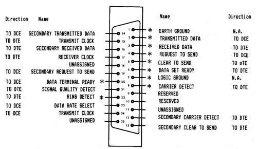
Only pins marked with an asterisk are connected in the LNW80.
Figure 9.0 - RS-232-C pin connector as defined
by EIA.
Some equipment which is attached to computers only uses
pins 2, 3 (data lines) and pin 7 (ground), while other
equipment may use the unassigned and reserved pins while still
going under the label 'RS-232-C Standardĺ.
The Baud
The BAUD, like many of the terms in RS232 jargon, has a bit
of history behind it. Named after Baudot, a pioneer in
telegraphic communications, the baud was the unit of
transmision speed for serial data communication. It
represented the number of half-dot cycles transmitted
continuously in one second (which is in fact the modulation
rate). We can think of the modulation rate as being the rate
at which a carrier wave is adjusted to accomodate data
transmission,
In the present-day scheme of things, when the data
signalling rate (measured in bits per second) is equal to the
modulation rate (expressed as baud), then the number of bits
transmitted per second is equal to the baud rate. (Long
sentence, that!). In our situation of asynchronous data
transmission, the baud rate is equal to the bit rate when one
stop bit is used.
Transmission Techniques
Inter-computer communication over a distance is almost
always achieved using serial data transmission, as the
communications,network is already there (the phone system).
As we have seen, data in the form of characters is encoded
in bits. The character length is optional here and can be
either 5, 6, 7 or 8 bits. This is to allow for various word
lengths that have arisen as standard over the years.
Each bit is transmitted as an electrical pulse along the
transmission line. The pulses are of a definite time
duration.
At the other end of the line, the receiver must somehow be
in synchronization with the pulses it receives. It must be
able to recognize when a bit starts and how long it lasts, and
when a character starts and ends. There are two modes of
operation to achieve synchronization between receiver and
transmitter:
- asynchronous operation
- synchronous operation
The LNW80 uses the asynchronous method, as do most
microcomputers.
With asynchronous communication, characters can be dumped
on to the transmission line raggle-taggle fashion, i.e., the
timing of character placement on the line is not important. In
allowing this, however, the receiver demands that each
character must be transmitted at a fixed rate and must be
framed with a start-bit and stop-bit(s).
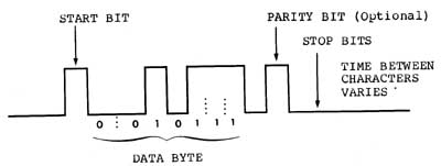
Figure 9.1 - asynchronous transmission showing
character with start and stop bits.
Connecting Equipment to the RS-232-C
When connecting equipment to the RS-232-C interface, we
must take into account whether it is:
Data Terminal Equipment (DTE), or
Data Communications Equipment (DCE).
DTE includes serial printers, teletypes and Decwriters. DCE
refers to modems.
As is, the LNW80ĺs RS-232-C interface is configured to
interact with DCE.
Serial Printer a the RS232
Serial printers and teletypes (DTE) have the same signals
on the RS232 cable as the LNW80. This is because Teletypes
were designed to interface directly with modems (as is the
LNW80) to act as a remote terminals. This means that there
will be conflicts on the RS232 lines since the printer's
outputs are the same as the computerĺs. Fortunately not all of
the RS232 signals are required when connecting to a serial
printer. Usually only the Transmit Data (TD) for the computer
is tied to the Receive Data (RD) of the printer along with the
chassis and signal ground (see table 9.0).
Some printers also require the use of handshaking lines.
Handshaking is the printers way of telling the computer that
it's buffers are full, and to hold off until it has printed
their contents. The computer must then wait until the printer
is ready to recieve data again. This signal should be received
on DSR (pin 6) and may be output by the serial printer on
either DTR (pin 20) or a separate RS232 handshaking signal.
For handshaking to operate properly, the handshaking signals
should be "ON" (+12V) when ready to receive more data, and
"OFF" (-12V) when busy. Check with the operations manual of
your printer if in doubt.
The following drawing illustates the lines connected. Some
serial printers require that CTS (pin 5) or DSR (pin 6) of the
printer be tied to either +12V or -12V for proper operation.
The operating manual for the printer should provide the
details.
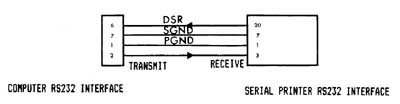
Figure 9.2 - Serial printer interfacing with the
computer.
Table 9.0 - Specifications for the LNW80's RS-232-C Interface
Pin Number Signal
1 PGND (protective ground)
2 TD (transmit data)
3 RD (receive data)
4 RTS (request to send)
5 CTS (clear to send)
6 DSR (data set ready)
7 SGND (signal ground)
8 CD (carrier detect)
20 DTR (data terminal ready)
22 RI (ring indicator)
TD -- Serial data is output to external device.
RD -- Serial data is received from external device.
RTS - Outputs a request to the external device to allow the
computer to transmit serial data.
CTS - Inputs a response from an external device to a RTS
saying that the external device is ready to receive serial
data.
DSR - Input to the computer saying that the receiving device
(at the other end of the telephone) is ready to receive from
the computer. In the case of a modem, this signal acknowledges
that it is not in test, talk or dial mode.
CD -- Input to the computer saying that the modem has sensed a
carrier signal over the telephone.
DTR - Output by the computer to tell the external device that
the computer is ready to transmit or receive serial data.
RI -- Input to the computer indicating that the modem has
received a ringing tone at the other end of the telephone.
Connecting a Modem
This device allows information to be transmitted from one
computer to another over the telephone lines. Telephone lines,
however, were designed, not for transmitting data, but with
the human voice in mind. The result is a system designed to
reproduce an analog signal representing the fluctuations of
the human voice in the frequency range 300 to 3400 Hertz
(cycles per second). Analog signals vary continuously with
time, rising and falling between high and low values. Digital
signals, on the other hand, have either a constant high value
or a constant low value at any one instant, changing from one
value to the other over a negligible period of time.
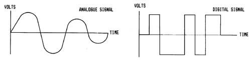
Figure 9.3 - Analogue and Digital Signals
The modem forges the gap between the two worlds. The word
modem is an acronym for MOdulator/DEModulator, indicating the
two functions a modem performs. When serial digital data from
the computer presents itself to the modem for transmission
over the telephone lines, it is first coded as an analog
signal, and then "applied" to a carrier wave resident in the
telephone network. This "applying" is called modulation.
A modulated signal arriving at the computer must be
demodulated. That is, the analog information imposed on the
carrier wave must be stripped off and converted into serial
digital information.
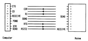
Figure 9.4 - Modem Interfacing With the Computer
Acoustic modems convert transmission data received into
audible tones which are fed to the computer via the earpiece
of the phone.
When data is going in the other direction, from the
computer to the transmission line, the modem converts data
into audible tones which are fed to the transmission line via
the phone mouthpiece.
A modem is DCE and, as a result, interfaces directly with
the RS-232-C serial communications interface. (Pin 2 on the
modem receives data, and pin 3 transmits). A cable with a male
DB25 plug is required to make this connection.
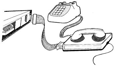
Figure 9.5 - Hooking Up a Modem
Switch Settings on the RS232C Interface
Located on the I/0 panel, next to the RS232 DB25 connector,
are 3 sets of small DIP switches, as shown in figure 9.6.
These switches are used to set the BAUD RATE and the UART (see
RS232 Operation 6 Programing) configuration settings (parity,
word length and number of stop bits).
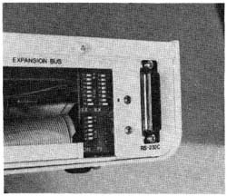
Figure 9.6 - Close up of RS232C dip switches.
The two BAUD RATE switches select the actual baud clocks (for
both receive and transmit) to the UART. The baud rate is not
software selectable on the LNW80 as it was on the TRS80 Model
I. Almost all TRS80 Model I software can still be used even if
it thinks it can set the baud rate under software control.
Only applications where the baud rates MUST be controlled by
the application program will the LNW80 not be compatible with
the TRS80 Model I . Some programs will attempt to display or
otherwise indicate the current baud rate setting under software
control. This is not possible on the LNW80 and this
information should be ignored.
The configuration switches for parity, word length, and
number of stop bits do not actually set these values directly
in the UART. These switches simply are present to allow the
application program to read back what they have been set to.
Since many existing TRS80 model 1 RS232 programs require that
these switches are present, it is also included on the LNW80.
These switches can be read by inputting from port E9H. For
more information on these configuration switches refer to the
section on programming the RS232 interface.
Transmitting and Receiving
The programmer has a number of things to consider before
communicating via the RS-232-C interface:
- Transmit and receive rates
- Parity
- Word length
- Start and stop bits
Setting Transmit and Receive Rates
For most applications the Transmit (TX) and Receive (RX)
switches (located next to the RS232 interface) will be both
set at the same value. Only one switch on the TX and one
switch on the RX should be on at any one time.
Table 9.1 - Setting Tx and Rx Rates
TX & RX Switch Baud rate
1 9600
2 2400
3 4800
4 1200
5 150
6 110
7 600
8 300
Setting Parity
When data is transmitted, errors often occur due to
electrical interference, or "noise," on the line. This may
result in an extra bit being included in a character, for
example. To provide a check on this, a parity bit is appended
to the word making the total number of "ones" in the word odd
or even, depending on whether you have chosen odd or even
parity for transmission.
The configuration switches on the I/0 panel are used to set
parity.
Table 9.2 - Setting Parity With the Configuration Switches
Parity Con Switch Position
Inhibit 1 Off
2 Off
Even 1 On
2 Off
Odd 1 On
2 On
Setting Word Length
A word (character) length of 5, 6, 7 or 8 bits may be used.
The reason for the various word lengths (just when we had
gotten used to 8 bits to a character) is that older machines
have different word lengths. For example, teletypes use a
5-bit word length.
Table 9.3 - Setting Word Length
Word Length Con Switch Position
5 4 On
5 On
6 4 Off
5 On
7 4 On
5 Off
8 4 Off
5 Off
Setting Stop Bits
You may select 1 or 2 stop bits. When using a 5-bit word
length, the configuration corresponding to 2 bits is, in
actual fact, 1.5 atop bits. You may well wonder how a half-bit
is arrived at. A hali-bit is represented by a time pulse half
that of full bit.
Table 9.4 - Setting Stop Bits
Stop Bits Con Switch Position
1 3 On
2 3 Off
Note: Configuration switch 6 is not used for anything.
RS-232-C Operation
The circuitry associated with the RS-232-C has as its
centerpiece a small dedicated processor, - the UART (Universal
Asynchronous Transmitter/Receiver). It is dedicated in the
sense that it has nothing else to do except to look after the
RS-232-C's goings on.
It is within the UART that the parallel data structure of
the computer is interfaced with the serial data structure of
the communications channel. The transmitter section of the
UART takes a parallel byte from the CPU bus (information
route) and converts it to a serial word with start, stop and
parity bits. The receiver section accepts a serial word from a
serial device complete with its adornment of stop, start and
parity bits, checks its validity, and then reconstitutes a
parallel byte.
Programming the RS232C Interface
In order for the UART to function to receive and transmit
serial data, a program within the LNW80 must communicate with
the UART writing commands, configuration information, and data
to its internal registers and reacting status and data back.
Here is a list of the requirements for programming the UART:
1. MASTER RESET
After power has been applied to the UART, it must be reset
before attempting to program any of the internal registers.
This can be done by outputting anything to port location E8
(hex). Here is an example of the assembly language source
code.
OUT (0E8H),A ;OUTPUT ANYTHING
2. CONFIGURATION OF UART
The UART will transmit and receive at the baud rate that is
provided by the switch settings but it must be told how it is
to transmit the serial data. Should there be PARITY? If so,
should it be EVEN PARITY or ODD PARITY? Should 5,6,7 or 8 bits
of data be transmitted? Should the STOP BITS be set at 1 or 2?
This information is programmed into the UART by certain bits
set or not set in the UART CONTROL REGISTER. This register is
addressed at port location EAH. The upper 5 bits of this
location determine the setting of this configuration while the
lower 3 bits are also used to set some of the handshaking
output lines.
The relationship between these switches and the UART
CONTROL REGISTER is such that by manually setting the
switches, your program can simply read the switches, mask the
lower 3 bits and then output that value to the UART CONTROL
REGISTER at EAH. This feature is provided for the purpose of
remaining compatible with programs written for the TRS80 Model
1 that read the switches and do not allow the user to select
this configuration under software control. Since both DOSPLUS
3.4 and LNWBASIC allow programming of the configuration AND it
is done in the BASIC programs provided at the end of this
section it is not recommended that new programs be written
that depend on these switches. Here is an example of how the
UART CONTROL REGISTER is set:
LD A,(CONFIG) ;load value from memory
OUT (EAH),A ; actually output to UART
CONFIG DEFB ; here is where the BASIC
; program put the
; configuration settings.
The example programs are provided at the end of this section
to illustrate how the configuration settings are selected from
a basic program.
Or if you are using the configuration switches...
IN A,(0E9H) ; INPUT FROM CONFIGURATION
SWITCHES
AND 0F8H ; MASK OFF LOWER 3 BITS
OR 05H ; SET THE LOWER 3 BITS AS DESIRED
FOR HANDSHAKING (BRK,DTR,RTS)
OUT (0EAH),A ; OUTPUT TO UART
3. TRANSMIT AND RECEIVE DATA
In order for the UART to transmit data, data must output
to the UART TRANSMIT REGISTER (EBH). Data can be input from
the UART RECEIVE REGISTER (EBH). Status concerning data
received, data transmitted, and errors can be read back on the
UART STATUS REGISTER (EAH). The status bits are defined in
figure 2 above. For more details in programming the UART,
refer to the LNW80 TECHNICAL REFERENCE MANUAL and the data
sheets on the TR1602B.
4. MODEM STATUS REGISTER
When communicating over voice grade telephone lines and
using a modem, various modem status conditions can be read
back. CTS, DSR, CD, RI can all be input at port location E8H.
See page 40 of the LNW80 Technical Reference Manual for the
bits associated with these status signals.
The assembly listing of the serial terminal program which
follows illustrates how the RS232 interface and the UART are
programmed.
;
; Assembly-language Listing of Terminal Program
;
0033 00010 DSP EQU 338
002B 00020 KBD EQU 2BH
FF70 00100 ORG 0FF70H
FF70 3E1C 00110 START LD A,1CH ;HOME CURSOR
FF72 CD3300 00120 CALL DSP
FF75 3E1F 00130 LD A,lFH ;CLEAR SCREEN
FF77 CD3300 00140 CALL DSP
FF7A 3E0E 00150 LD A,0EH ;TURN ON CURSOR
FF7C CD3300 00160 CALL DSP
FF7F D3E8 00170 IUART OUT (MR),A ;RESET UART WITH
ANYTHING
FF81 DBE9 00180 IN A,(CONFIG) ;GET TERM
CONFIG
JUMPERS
FF83 E6F8 00190 AND 0FSH ;MASK LOWER 3 BITS
FF85 F605 00200 OR 5H ;SET BRK, RESET,
DTR, SET RTS
FF87 D3EA 00210 OUT (CTRL),A;PUT IN CONTROL
REG
FF89 DBEA 00220 RSRD IN A;(CTRL)
FFSB CB7F 00230 BIT 07H,A ;IS RECEIVE DATA
AVAILABLE
FFSD 2817 00240 JR Z,SEROUT
FFSF DBEB 00250 IN A;(DATA) ;GET DATA
FF91 B7 00260 OR A
FF92 2812 00270 JR Z;SEROUT ;IF NO INPUT LOOK
TO OUT
FF94 E67F 00280 AND 7FH ;STRIP PARITY
FF96 FE60 00290 CP 60H
FF98 FA9DFF 00300 JP M,AAT
FF9B E65F 00310 AND 5FH ;LOWER TO UPPER
CASE
FF9D FE0A 00320 AAT CP 0AH
FF9F 28E8 00330 JR Z,RSRD
FFA1 CD3300 00340 CALL DSP ;DISPLAY
CHARACTER
FFA4 18E3 00350 JR RSRD
FFA6 CD2B00 00360 SEROUT CALL KBD ;INPUT FROM
KEYBOARD?
FFA9 B7 00370 OR A
FFAA 28DD 00380 JR Z,RSRD ;IF NOTHING THEN
BACK TO INPUT
FFAC FE05 00390 CP 5H
FFAE F2B9FF 00400 JP P,NOSPCH ;NOT A SPECIAL
CHARACTER
FFB1 21CSFF 00410 LD HL,SPCHTB-1 ;SPECIAL
CHARACTER
TABLE
FFB4 4F 00420 LD C,A
FFB5 0600 00430 LD B,0H
FFB7 09 00440 ADD HL,BC ;HL POINTS TO
SPEC. CHARACTER
FFB8 7E 00450 LD A,(HL) ;GET SPECIAL
CHARACTER CODE
FFB9 FE1A 00460 NOSPCH CP 1AH
FFBB 28CC 00470 JR Z,RSRD ;IS SHIFT DOWN
ARROW? IGNORE
FFBD 4F 00480 RSWR LD C,A ;SAVE DATA
FFBE DBEA 00490 IN A,(CTRL) ;GET UART STATUS
FFC0 CB77 00500 BIT 06H,A ;IS TRANSMIT
REGISTER EMPTY
FFC2 28F9 00510 JR Z,RSWR ;IF NOT LOOP
FFC4 79 00520 LD A,C ;PUT CHAR IN A
FFC5 D3EB 00530 OUT (DATA),A gOUTPUT CHAR
FFC7 18C0 00540 JR RSRD ;BACK TO INPUT
ROUTINE
FFC9 03 00550 SPCHTB DEFB 03H
; DEFAULT: EOT-CNT "A"
FFCA 1B 00560 DEFB 1BH
;DEFAULT:ESC-CNT"B"
FFCB 7C 00570 DEFB 7CH ;DEFAULT:VERT BAR
-CNT"C"
FFCC 7F 00580 DEFB 7FH
;DEFAULT:DEL-CNT"D"
00E8 00720 MR EQU 00E8H
00E9 00730 CONFIG EQU 00E9H
00EA 00740 CTRL EQU 00EAH
00KB 00750 DATA EQU 00EBH
FF70 00770 END START 00000 TOTAL ERRORS
Getting the Most From the RS-232-C
The RS-232-C may well be one of the most important features
on your LNW80. It allows you to communicate with your local
community college computer (educational budget permitting), or
work computer, your LNW80 acting as a terminal. Thus you can
interact with large computer systems from your home.
The ramifications of this kind of setup could have dramatic
effects on society in the not so distant future. Ponder for a
moment if you will, on the work habits of people in
metropolitan areas. Every morning large numbers of citizens
from the suburbs pile into their automobiles and drive towards
downtown. Once there, they assume positions at desks where
they write on paper and pass information, one to the other,
again on paper.
Adding up the cost of this kind of modus operandi, a number
of inefficiences come rushing to mind. Think of the time spent
commuting and the cost of this on both pocket and environment.
The astronomical cost of harboring thousands of people in one
big building also springs to the fore. If only we could
communicate, perform more direct accounting and commit
information to store without all of this paper!
Let's be glib here. Instead of spending the tons of money
(literally) on office construction and maintenance, why not
give all of the employees a microcomputer and modem (I have
just the system in mind!) and the resources for a small bureau
at home. The employees could log on every morning to a central
computer and find out what was wanted of them today. They
could submit work to the computer, which would spout out the
facts to the company president and his aides. The considerable
savings on gasoline could be used to improve the
communications network.
This rather loosely strung together train of thought hints
at the real possibilities the RS-232-C communications unit
could present.
BASIC RS232C Serial Printer & Terminal Programs
The following program can be used as a terminal program,
which allows your computer to communicate with other computers
via a modem.
10 REM SERIAL CRT TERMINAL PROGRAM
20 REM
30 REM This program allows the use of the LNW80 computer
40 REM system as a CRT terminal. This program may also be
50 REM used for testing the serial interface by connecting
60 REM pins 2 & 3 of the RS232C DB25 connector together.
65 REM BE SURE TO SET HIGH MEMORY TO 65390
70 FOR X=-144 TO -52
80 READ D
90 POKE X,D
100 NEXT X
110 POKE 16526,112 '070H
120 POKE 16527,255 '0FFH
130 A=USR(N)
200 DATA 62,28,205,51,0,62,31,205,51,0,62,14,205,51,0,211
210 DATA 232,219,233,230,248,246,5,211,234,219,234,203,127
220 DATA 40,23,219,235,183,40,18,230,127,254,96,250,157,255
230 DATA 230,95,254,10,40,232,205,51,0,24,227,205,43,0,183
240 DATA 40,221,254,5,242,285,255,33,200,255,79,6,0,9,126
250 DATA 254,26,40,204,79,219,234,203,119,40,249,121,2ll
260 DATA 235,24,192,3,27,124,127
Serial Printer Program
10 REM BASIC SERIAL PRINTER PROGRAM
30 REM This program allows the use of a serial printer
40 REM with the LNW80. This program is left in memory
50 REM unaltered by BASIC and user programs. The program
60 REM is executed during each LPRINT and LLIST statement
70 REM Handshaking is supported as the software reads the
71 REM the printer busy (DSR) before outputting a
72 REM character. If your printer does not support
73 REM handshaking, change line number 340 to:
74 REM 340 DATA 219,232,203,119,0,0,219,234
75 REM BE SURE TO SET HIGH MEMORY TO 65278 BEFORE
76 REM entering BASIC.
77 REM
78 REM
80 CLS:PRINTCHR$(23):PRINT"LNW RESEARCH CORP.":PRINT"BASIC
SERIAL PRINTER PROGRAM"
90 FOR X=-256 TO -207
100 READ D
110 POKE X,D
120 NEXT X
130 A$="E":P=128:L=0:WL=1:SB=7:B=32
140 'INITALLY SET FOR 1 START BIT, SEVEN BITS DATA, EVEN
PARITY,ONE STOP BIT
150 POKE 16421,2:POKE 16422,0:POKE 16423,255 'POKE NEW DCB
160 FORZX=1T0600:NEXTZX:CLS:PRINT"CONFIGURATION MENU":
PRINT: PRINT"RS232 CONFIGURATION SETTINGS"
170 PRINT"1) PAR1TY (E-EVEN)g(O-ODD),(D-DISABLED) ";A$
180 PRINT"2) STOP BITS ";WL
190 PRINT"3) WORD LENGTH ";SB
200 PRINT"4) RUN TERMINAL PROGRAM":PRINT"SELECT FUNCTION"
210 Z$ =INKEY$:IFZ$=""THENGOT0210ELSEIFZ$="1"THENGOT0220ELSE
IFZ$=" 2" THENGOT0270ELSEIFZ$="3"THENGOT0240ELSEIFZ$="4"
THEN GOT0290ELSE GOT0210
220 P=0:INPUT"PARITY EVEN (E), ODD (0), OR DISABLED (D)";
A$:IFA$="E" THENP=POR128ELSEIFA$="0"THENP=PAND127ELSE
IFA$="D"THENP=POR8 ELSEGOT0220
230 GOTO 160
240 INPUT"WORD LENGTH (5,6,7,8)";SB:IF SB<5THEN240ELSE
IFSB>8THEN240
250 IFSB=5THENB=0ELSEIFSB=6THENB=64ELSEIFSB=7THENB=32ELSE
IFSB=STH ENB=96
260 GOT0160
270 INPUT"STOP BITS (1 OR
2)";WL:IFWL>2THENGOT0270ELSEIFWL
SECTION 10: MEMORY UTILIZATION
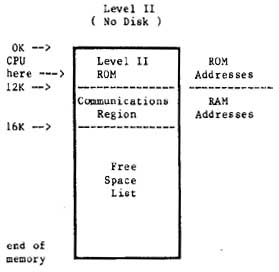
A Look at Memory in a Non-Disk System
The computer is now operating out of ROM using the Level II
BASIC language.
On power up we have 64K of memory address space in the
machine. 12K of this is Read Only Memory (ROM), which we
cannot use to hold programs or data. In addition, the computer
takes up just over 2K bytes of memory space which it uses to
operate the keyboard, the video, I/0 routines and other
computer "housekeeping" functions. Almost 2K is not used for
anything.
So, of the 64K of memory space that we started out with,
the computer has earmarked 16K for its own purposes. This
leaves us, the programmers, with 48K or thereabouts. See
figure 10.0 for a schematic presentation of memory
allocation.
Figure 10.0 - Simple Rectangular Memory Block Diagram.
A Look at Memory in a Disk System
With system start-up from disk, the DOSPLUS disk operating
system is loaded from disk into RAM. The system doesn't just
load into memory at any old position. No, the DOS loads in at
the 16K mark in memory and extends for 5K to 21K. The memory
up to 16K is the same as that in a non-disk system. In fact
the DOS enhances the ROM based system ay acting in cooperation
with it. Figure 10.1 is a schematic drawing of memory
allocation in a disk system.
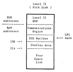
Figure 10.1 - Memory block diagram for a disk
system. (Before BASIC is called).
A disk operating system takes up more memory than the ROM
based system. However, the availability of a large amount of
quickly accessible storage on disk, more than compensates for
the extra 5K of memory we have sacrificed.
High Memory Protection
The BASIC interpreter uses as much memory as you will allow
it. In a ROM based system, BASIC uses a variable amount of
space beyond the 16K region, where it stores tables and
variables. In the case of a disk system, these tables and
variables are stored just beyond the 26K region. In both
cases, BASIC also stores information way up there in high
memory (in the 40K+ region).
You may put a ceiling on BASIC's use of memory by replying
to the MEMORY SIZE? question on power up or reset. By replying
with say 32768, you will keep BASIC out of memory locations
above 32K. This is important if you want to use
assembly-language programs.
For a memory map showing how Level II BASIC uses memory,
see Appendix D of the Radio Shack Level Il manual. This is not
vital information if you are a beginner, but it is important
if you are an assembly-language enthusiast.
SECTION ll: CHOOSING AND USING A DISK OPERATING SYSTEM
Introduction
The LNW80 supports a wide number of disk operating systems
(DOS). A full list is supplied in Table 11.0. This versatility
towards software will be welcome news to those programmers who
want to continue using the same software that wooed them
towards microcomputers in the first place. However, the first
time owner may find the choice of DOSes a bit bewildering, and
for this reason we include DOSPLUS 3.4 in the LNW80 package.
We think this is a well-documented and easy to use DOS.
Knowing full well that the first operating system that you
come to know generates a feeling not unlike that towards your
first car, this section includes detailed instructions on how
to set up a disk system for a number of DOSes.
But first, as a backdrop (hey, this is southern
Californian) to all of this technical mumbo jumbo, letĺs take
a vague look at microcomputer operating systems and their
background. (For a detailed description of a disk operating
system, see the introduction to this manual).
Important Aspects of a DOS
From a programmerĺs point of view, a DOS should be
transparent and fast. Transparent means that it should perform
the various data manipulations in such a way that the
programmer is hardly aware of what's going on. When the DOS
needs to look up system tables, or bring another system module
from disk into RAM (overlaying), we, the programmers, want it
to do so without bothering us as we slave away at the
keyboard. We would also like to have some data recovery
facilities, in the event that the DOS tells us it canĺt read a
disk sector. Ideally, the DOS should do all of this using a
minimum of valuable RAM.
A very important aspect of any operating system is its
documentation. If the documentation is not very clear, and you
can't find out how to use the system, or you find yourself
encountering difficulties which are not explained, then the
system ends up being of little use and a real pain in the
byte.
A Brief History of the TRS80 Model I Operating Systems
Since the introduction in 1978 of tba TRS80 Model I
microcomputer and its disk operating system, TRSDOS, a wide
variety of operating systems have been developed to operate on
the TRS80 Model I. These systems were developed, for the most
part, to improve upon a poor TRSDOS 2.1. One of the operating
systems to emerge was NEWDOS. This operating system was
written because its owners, Apparat Inc., needed a DOS for
their own internal use that actually worked. Before long,
others heard that a DOS really did exist that worked and
Apparat became a DOS company.
Meanwhile, the original author of the Radio Shack TRSDOS
2.1, Randy Cook, began improving on what he had written and
created what would be known as VTOS 3.0. He marketed the DOS
under the company name of Virtual Technology Inc. Apparat
continued to improve the NEWDOS and released NEWDOS 2.1,
NEWDOS+, and NEWDOS80 1.0. VTOS 3.0 evolved to VTOS 4.0 as
more features were added.
At about the same time, a young programmer in Florida had
written a DOS for both single-density and for the new
double-density adaptor from Percom Data Co. This DOS became
widely known as DOSPLUS 3.2 and 3.2D, and was marketed by a
company known as Microsystems Software. This DOS evolved to
3.3D, which became the standard DOS supplied with the
LNDOUBLER. At about the same time, other DOS systems were
springing up almost from nowhere. The DOS WAR had just begun.
Radio Shack did not sit still during the DOS WAR. They
improved upon TRSDOS and finally developed a DOS which both
worked and offered some usable features, - TRSDOS 2.3.
VTOS was sold to Lobo Drives fox use on their LX80
interface, and with a major effort in both programming and
documentation, LDOS 5.0 and 5.1 emerged. LDOS was a powerful
"device independent" system with the features of VTOS, but
without the bugs. LDOS uses the same syntax as TRSDOS, but has
many additional features and capabilities. With the LDOS PATCH
(available from your LNW dealer), diskettes that were written
using the LX80 interface under LDOS (5-1/4" and 8" double or
single-sided, single or double-density) can be read or written
to with an LNW80 or LNDOUBLER 5/8 (with a speed-up kit) and
the appropriate disk drives under LDOS 5.0 or 5.1.
With the emergence of the standard of double-density,
Apparat released NEWDOS80 version 2.0. This DOS was by far the
most powerful and flexible system ever developed. It would
interface not only 5-1/4" disk drives but, with the use of the
LNDOUBLER 5/8, would interface both single and double-density
(double-density required a speed-up kit on the TRS80 Mod I)
8-inch floppy disk drives, The only drawback of this
outstanding system was the complexity of operation and the
differences in syntax between TRSDOS 2.3 and NEWDOS.
Microsystems Software had also developed a new DOS with the 8
inch and hard drive features, as well as adding many other
powerful functions. This was to be called DOSPLUS 3.4.
DOSPLUS 3.4 has become the standard DOS supplied with both
the LNW80 and the LNDOUBLER 5/8 double-density adaptor. This
DOS has the great advantage of simplicity. It matches TRSDOS
syntax, has clear and concise documentation, and thus, is a
good DOS for the first-time owner.
Looking at the Various Disk Operating Systems
There are two important points to note at this juncture:
NOTE 1
Some of the operating systems that will operate on the
TRS80 will not support the 4MHz CPU speed of the LNW80. Some
of the operating systems may operate at the 4HMz speed with
special configuration of the operating system. Others will
operate at the high speed, but will not properly boot (reset)
at the high speed. For these reasons, we recommend that the
HIGH/LOW speed switch on the keyboard be set to LOW (down)
before booting a previously untested DOS. Table 11.0 lists the
known compatible systems.
NOTE 2
The double-density disks created on the following DOSes are
not necessarily read/write compatible with each other. Of all
the DOSes listed, only MULTIDOS has the ability to read the
formats of the other operating systems (note that MULTIDOS
will not read double-sided or 8 inch formats). Single-density
disks created using any of the operating systems listed in
Table 11.0 are, for the most part, fully interchangeable.
Table 11.0 - LNW80 Compatible DOSes
OPERATING
SYSTEM NAME |
 4MHZ
OK |
5-1/4"
SD
|
DISK DRIVE SUPPORT
 5-1/4"  | 8"    | 8"
DD | SD | DD |
DUAL
|
DOSPLUS 3.2S  NO     S,D                               YES
DOSPLUS 3.2D  NO     D         S	               YES
DOSPLUS 3.4   YES    D         S,D       D       S,D   YES
DBLDOS        NO     D         S,D                     YES
EZ-DOS        YES    S,D       S,D       S,D     S,D   YES
LDOS 5.0      YES    S,D       S,D(2)    S,D(2)  D(2)  YES
LDOS 5.1      YES    S,D       S,D       S,D(2)  D(2)  YES
MULTIDOS      YES    S,D       S,D
NEWDOS 2.1    NO     S,D
MEWDOS+       NO     S,D
NEWDOS80 1.0  NO     S,D       S,D(l)                  YES
NEWDOS80 2.0  YES    S,D       S,D       S,D     S,D   YES
OS-80         NO     S,D       S,D                     YES
TRSDOS 2.3    NO     S,D
ULTRADOS      NO     S,D
VTOS 4.0 NO S,D S,D(1) YES |
S = system disk, D = data disk,
SD = single-density, DD = double-density
DUAL = dual-sided drive support
1 = Double Zapii from Software Etc. required
2 = LDOSPATCH from LNW Research required
The Top Five Operating Systems
TRSDOS 2.3
DOSPLUS 3.4
NEWDOS80 U 2.0
LDOS 5.0 AND 5.1
MULTIDOS
TRSDOS 2.3
While probably the most popular of all the DOSes, TRSDOS is
the simplest, will only operate with single-density, 5-1/4"
35-track floppy drives and has a limited BASIC as well as a
limited set of library commands. The TRSDOS manual is by far
the finest piece of documention written on any of these
operating systems and is available at Radio Shack stores
around the world:
TRSDOS & DISK BASIC Reference Manual
For the TRS80 TRSDOS 2.3
Disk BASIC Version 2.2
LNWBASIC is fully compatible with the DISK BASIC in TRSDOS
2.3.
DOSPLUS 3.4
DOSPLUS 3.4 is a powerful, easy-to-use system that is well
documented and is fully TRSDOS compatible. DOSPLUS 3.4 was
supplied on either a
5-1/4 inch 35 track double-density system disk, OR
An 8 inch double-density 77 track system disk
with your LNW80 computer. In order to make a back-up copy,
simply use the BACKUP command while referring to the first six
pages of the DOSPLUS 3.4 USER manual.
Eight-inch Data Disks
In order to tell the operating system that you have
installed an eight-inch drive on your system, DOSPLUS 3.4
requires that you use the CONFIG command. The following
example assumes that an eight-inch drive is installed at
position 3.
1. For Eight-inch Single-sided type:
CONFIG :3 (SIZE=8,SIDES=1)
For Eight-inch Double-sided type:
CONFIG :3 (SIZE=8,SIDES=2)
2. Next type:
CONFIG (SAVE)
The CONFIG command can also be used to set the LNW80
computer to inverse video on power up. This is done by typing
CONFIG :0 (MODE=1)
and then typing
CONFIG (SAVE)
To restore to standard video on power up, type:
CONFIG :0 (MODE=0)
and then:
CONFIG (SAVE)
For more details on the CONFIG command, refer to page 32 of
the DOSPLUS 3.4 USER MANUAL.
DOSPLUS 3.4 and LNWBASIC
LNWBASIC is 100% compatible with DOSPLUS 3.4. In order to
bring a program written in LNWBASIC to execute automatically,
create a DO file using the BUILD command. For example, say we
wanted to automatically power up and run a demonstration
program called DEMO/LNW. First we would create a DO file like
this:
BUILD DEMO:0
After the system asks you to type in commands of 64
characters or less:
LNWBASIC
RUN "DEMO/LNW"
Using the AUTO library command, now make the DO file
execute on BOOT or power up:
AUTO DO DEMO
Now the demo program will run automatically when your
DOSPLUS disk with LNWBASIC is booted.
NEWDOS80 VERSION 2.0
BEFORE ATTEMPTING TO USE THIS OPERATING SYSTEM,
READ THIS SECTION CAREFULLY!
This operating system is by far the most powerful of the
operating systems that will run on the LNW80 computer. It has
so many options and features that it can leave many owners
lost attempting to sift through the huge manual. The manual,
like the operating system, is not intended for the first-time
computer owner, and if you can read faithfully through the
second page, you are instructed to spend a couple of hours
reading through the manual before even touching the diskette.
It is the first 50 pages in the manual that provide the key to
the operation of the DOS, and we recommend that you slowly
read through these first two sections before even attempting
to use the DOS.
NEWDOS80 System Configuration
When using NEWDOS80 V2 at the high CPU speed (HIGH/LOW UP
and AUTO SWITCHING DOWN) the SYSTEM option BJ must be set to
3. In order to set this, boot a copy of the MASTER system disk
(not write protected) with the HIGH/LOW switch set to the low
position. Type:
SYSTEM,0,BJ=3
Now RESET your computer again before proceeding. You may
now use this system disk (or copies made from it) with the
HIGH/LOW switch set to the high position (mandatory for 8 inch
drives).
Disk Drives and NEWDOS80 Version 2.0
NB: Proper 8 inch operation requires that ZAPS up to and
including 047 must be applied to the NEWDOS80 system disk. If
you are in doubt, contact Apparat Inc. or your computer
dealer. LNW Research cannot distribute this zap information.
Also, since proper electrical configuration of your drives
must be assured BEFORE proceed, you must have operated your
drives under DOSPLUS 3.4 before attempting to use any other
operating system.
NEWDOS80 2.0 allows the programmer a tremendous degree of
flexibility in choosing the type of disk drive to be used with
the system. Disks can be set as single-density,
double-density, any number of tracks, 5-1/4 and 8 eight-inch,
single or double-sided. Configuring the operating system such
that it knows what type of drives you have connected to your
LNW80 is accomplished with the PDRIVE library command. This is
a more complex form of the CONFIG command in DOSPLUS. Section
2.37, on pages 2 - 33 of the NEWBOS80 manual, details just how
to use this command. You will notice that LNW has its own
interface setting TI=E. This means that although your system
will boot with the TI=A setting, as set on the diskette
supplied from Apparat, in order to use double-density or 8
inch disk drives, the TI=E flag must be set for ALL of the
drives (all 10 of them) REGARDLESS of whether or not you have
a drive at that position. Double-density, single-density, 5
inch, 8 inch, single-sided, dual-sided system disks can be
made by correctly setting the PDRIVE specification and using
the correct form of the COPY command. To simplify things a
bit, the following sections will illustrate just how to make
some of the most common forms of SYSTEM as well as DATA
disks.
Backing Up
Before proceeding, lets make sure that we have made a
"back-up" of our one and only copy of the NEWDOS80 V 2 SYSTEM
DISK. How to make a backup is found on pages 1 - 4. Since
there is no BACKUP command, the COPY command is used:
for SINGLE drive system configuration
COPY,0,0,,FMT,USD
for MULTIPLE drive configuration
COPY,0,l,,FMT,USD
Now, using the backup copy of the operating system, a
double-density system disk can be made.
Making a NEWDOS80 2.0 Double Density 5-1/4" System Disk
The NEWDOS80 VERSION 2.0 system disk comes in
single-density format and requires that a DOUBLE-DENSITY
SYSTEM DISK be created using the procedure which follows. Read
the section in the NEWDOS80 2.0 manual on PDRIVE specification
(pages 2 ľ 33) before proceeding, and do not attempt to create
a double-density system disk without reading the following
instructions. Going to double-density is not as simple as just
changing the pdrive specifications for your single-density
diskette. A NEW diskette must be created!
Instructions
l. Insert the backup NEWDOS80 system disk into drive 0
and put the master system disk away.
2. After each of the following commands in STEP 3,the
system will respond by listing the PDRIVE specifications for
all drives and also print an error message. Wait for the
NEWDOS80 READY prompt and then type in the next command. Do
not reset the computer until instructed to. Resetting the
computer with an error in the PDRIVE specifications will
result in the destruction of your system diskette.
3. Type in the following commands and then return
:
PDRIVE 0,0,TI=E,TC=40
PDRIVE 0,l,TI=EK,TD=E,TC=39,SPT=18
PDRIVE 0,2=0
PDRIVE 0,3=0
PDRIVE 0,4=0
PDRIVE 0,5=0
PDRIVE 0,6=0
PDRIVE 0,7=0
PDRIVE 0,8=0
PDRIVE 0,9=0,A
The error message should disappear after the last entry is
made. If it does not, redo the entire procedure, exercising
more care this time. Once this process is complete, the DOUBLE
DENSITY system disk can be generated.
Multiple Drive Systems
1. Insert a blank diskette in drive 1
2. Type COPY 0 1,,CBF
Type "Y" to FORMAT prompt
and "Y" to the SYSTEM 0 prompt.
Enter return
to the DESTINATION DRIVE prompt.
3. When the copy is done, type DIR :1
You should be able to verify that there are considerably
more granules (grans) free on the new double-density disk than
on the single-density system disk in drive 0.
4. Remove the system disk from drive 0 and replace it
with the newly created double-density system disk from drive
1. Press RESET and now the double-density disk should boot.
Type:
PDRIVE 0
Notice that the pdrive specifications for both drive 1 and
drive 0 are the same (double-density).
Single Drive Systems
With the system disk in drive 0 type:
COPY,0,0,,FMT,USD,CBF,DPDN=l
The system will instruct you when to remove the source disk
and insert the destination (blank) disk. Follow as instructed,
remembering that your original diskette is the source and the
blank diskette is the destination diskette. Usa great care not
to become confused as to which disk is which since you will
have to do this several times.
When the copy is complete, replace the system disk in drive
0 with the destination diskette and reset the system. Type DIR
. More grans should be available on this newly created
disk.
Special Note
NEWDOS80 2.0 does not have automatic density recognition as
does DOSPLUS 3.3D, 3.4 and the zaps from CIRCLE J. This means
that if you would like to look at the directory or copy files
to and from or execute a file from a single-density diskette,
you cannot do it without first changing the PDRIVE
specifications on your NEWDOS80 2.0 drive 0 disk. Automatic
density recognition for NEWDOS80 2.0 is available from TAS
(The Alternate Source, 704 North Pennsylvania Ave., Lansing,
MI., 48906 (517) 482-TAS0) under the product name of DDSD/CMD.
Without this program, switching PDRIVE specifications manually
can be done by typing:
PDRIVE 0,1=3,A
This assumes that drive 1 is the drive that the
single-density disk will be inserted into. To change back to
double-density on drive 1, simply type:
PDRIVE 0,1=0,A
This sets (or equates) the pdrive specifications for drive
1 to be the same as drive 0 (double-density).
Other Types of Drives
NEWDOS80 supports any type of disk drive from single-sided,
single-density five inch to dual-sided eight-inch
double-density. Even system disks can be made on any drive
type. This flexibility offers potential problems for the
uninitiated owner. The following should help clear up some
possible points of confusion:
Double-sided Disk Drives
Going to dual-sided disk drives is similar to upgrading to
double-density. A NEW diskette must be created using the
correct PDRIVE spec.
Eight-inch Disk Drives
For proper double-density operation, the HIGH/LOW key on
the keyboard must be UP and the AUTO SWITCHING control on the
I/0 panel. By setting the PDRIVE specs as listed below,
eight-inch system or data disks can be made.
Making an Eight-inch System Disk with NEWDSO80
An eight-inch single or double-sided, single or
double-density system disk can be created from the NEWDOS80
system disk created above (with NO write-protect tab). The
following example assumes that an eight-inch drive is on drive
2 and a five-inch drive is on drive 0.
1. Depending on which type of disk you want to create type
one of the following:
For
Single-density, 77 Track, Single-sided Eight-inch type:
PDRIVE,0,2,TI=EH,TD=B,TC=77,SPT=l7,TSR=3,GPL=3,DDSL=17,DDGA=6
For
Single-density, 77 Track, Double-sided Eight-inch type:
PDRIVE,0,2,TI=EH,TD=D,TC=77,SPT=34,TSR=3,GPL=3,DDSL=17,DDGA=6
For
Double-density, 77 Track, Single-sided Eight-inch type:
PDRIVE,0,2,TI=EHK,TD=F,TC=76,SPT=30,TSR=3,GPL=3,DDSL=17,DDGA=4
For
Double-density, 77 Track, Double-sided Eight-inch type:
PDRIVE,0,2,TI=EHK,TD=H,TC=76,SPT=60,TSR=3,GPL=3,DDSL=17,DDGA=4
2. The complete PDRIVE table should have been displayed. If
an error was indicated, then either you do not have the proper
PDRIVE settings OR you do not have ZAPS up to and including
047 installed on your system disk.
3. RESET the computer.
4. Install a blank 8 inch disk in drive 2 and type:
COPY,0,2,,CBF,NDMW,FMT
5. Once the format and copy are complete, this new
eight-inch disk drive can be booted by:
a. Changing the drive select such that an eight-inch
drive is set for drive 0.
b. Change the position of the 5/8 switch on the
LNDOUBLER 5/8 circuit board inside the LNW80 such that it is
set to the 8 position. This means the switch lever faces AWAY
from the floppy disk connector.
c. Reset the computer (make sure that the computer has
had power applied for at least 10 seconds).
77 or 80 Track 5-1/4 Inch Drives and NEWDOS80
If you have ONLY this type of drive, a special system disk
must be obtained from Apparat since the standard 35 track
diskette cannot be used as a system disk on reset.
List of the Most Common NEWDOS80 PDRIVE Specifications
System Disks
SIZE DENSITY TRACKS SIDES TI TD TC SPT TSR GPL DDSL DDGA
5 SINGLE 35 1 E A 35 10 3 2 17 2
5 SINGLE 35 2 E C 35 20 3 2 17 2
5 SINGLE 40 1 E A 40 10 3 2 17 2
5 SINGLE 40 2 E C 40 20 3 2 17 2
5 SINGLE 80 1 E A 80 10 3 2 35 2
5 SINGLE 80 2 E C 80 20 3 2 35 2
5 DOUBLE 35 1 EK E 34 18 3 2 17 2
5 DOUBLE 35 2 EK G 34 36 3 2 17 2
5 DOUBLE 40 1 EK E 39 18 3 2 17 2
5 DOUBLE 40 2 EK G 39 36 3 2 17 2
5 DOUBLE 80 1 EK E 79 18 3 2 35 4
5 DOUBLE 80 2 EK G 79 36 3 2 35 4
8 SINGLE 77 1 EH B 77 17 3 3 17 6
8 SINGLE 77 2 EH D 77 34 3 3 17 6
8 DOUBLE 77 1 EHK F 76 30 3 3 17 4
8 DOUBLE 77 2 EHK H 76 60 3 3 17 4
Data Disks
When using diskettes simply for storing data, the following
formats will increase slightly your storage space over the
above system disk capacity. If possible, stay with the above
formats and STANDARDIZE on the formats that you use such that
you do not forget which PDRIVE spec is used on which diskette.
This will reduce frustration later when reviewing old
diskettes. Use the FORMAT command in NEWDOS80 with the correct
PDRIVE specification to properly initialize data diskettes
(even when using the above formats).
SIZE DENSITY TRACKS SIDES TI TD TC SPT TSR GPL DDSL DDGA
5 SINGLE 35 1 E A 35 10 3 2 17 2
5 SINGLE 35 2 E C 35 20 3 2 17 2
5 SINGLE 40 1 E A 40 10 3 2 17 2
5 SINGLE 40 2 E C 40 20 3 2 17 2
5 SINGLE 80 1 E A 80 10 3 2 35 2
5 SINGLE 80 2 E C 80 20 3 2 35 2
5 DOUBLE 35 1 E E 35 18 3 2 17 2
5 DOUBLE 35 2 E G 35 36 3 2 17 2
5 DOUBLE 40 1 E E 40 18 3 2 17 2
5 DOUBLE 40 2 E G 40 36 3 2 17 2
5 DOUBLE 80 1 E E 80 18 3 2 35 2
5 DOUBLE 80 2 E G 80 36 3 2 35 25
8 SINGLE 77 1 EH B 77 17 3 3 17 6
8 SINGLE 77 2 EH D 77 34 3 3 17 6
8 DOUBLE 77 1 EH F 77 30 3 3 17 4
8 DOUBLE 77 2 EH H 77 60 3 3 17 4
LNWBASIC and NEWDOS80 2.0
LNWBASIC is fully compatible with NEWDOS80 2.0. In order to
run LNWBASIC, simply type: LNWBASIC. To chain automatic
execution of programs written in LNWBASIC, the programmer can
either chain together the commands in a DO file (like DOSPLUS
3.4) using the CHAINBLD/BAS program or a simple one-line
command can be used to bring up the program:
LNWBASIC RUN"DEMO/LNW"
LDOS 5.0 AND 5.1
Before attempting to use this DOS, please read this section
carefully!
NOTE: LDOS WILL NOT BOOT AT THE HIGH CPU SPEED
OF THE LNW80 COMPUTER ALWAYS MAKE SURE THAT THE
HIGH/LOW SWITCH IS DEPRESSED PRIOR TO RESETTING
THE SYSTEM
LDOS is a powerful and well-documented operating system for
the LNW80. It is a good system for the first-time owner since
it uses the same syntax as TRSDOS 2.3 yet offers quite a few
additional features. As supplied from Logical Systems Inc.,
LDOS will operate with 5 inch single or double-density, single
or double-sided disk drives. LDOS is supplied on two
single-density, single-sided diskettes. These diskettes should
be backed up according to the instructions supplied in the
owner manual's introductory section BEFORE using LDOS.
Disregard the constant mention of the LX80 interface when it
is referenced in their manual. This interface can only be used
with the TRS80 Model I. A program called LDOSPATCH is
available from your dealer. This program allows the LNW80
computer and LDOS to operate with 5 or 8 inch disk drives in
single or double-density and single and double-sided operation
fully compatible with the LX80 interface. LDOSPATCH also
provides AUTO DENSITY recognition such that either single or
double-density diskettes can be read with the density set
automatically by the operating system.
Setting the LDOS System
The SYSTEM library command allows the programmer to
configure many parameters in LDOS. The system FAST command
does allows the LNW80 to operate (except on reset) at the high
CPU speed. It unfortunately has one bad side effect, - it
turns on inverse video. This can be eliminated by outputting
OUT 254,0 during BASIC.
LNWBASIC and LDOS
The resident DISK BASIC on LDOS is called LBASIC. Its name
on the diskette creates an incompatibility with LNWBASIC. In
order to use LNWBASIC with LDOS, LBASIC must be renamed in the
directory. Type in the statement below exactly as shown.
RENAME LBASIC/CMD.RS0LT0FF TO BASIC/CMD
Note: The character between the S and L and again between
the T and F is a ZERO and not "O".
The mechanism for bringing up a program written in LNWBASIC
to automatically run (CHAIN or AUTO) DOES NOT WORK in LDOS.
THIS DOES NOT MEAN THAT LNWBASIC WILL NOT WORK IN LDOS, IT
MEANS THAT AUTOMATIC EXECUTION OF A BASIC PROGRAM WRITTEN IN
LNWBASIC CANNOT BE DONE.
Using Eight-inch and Double-density
For proper double-density operation on EIGHT INCH drives
the HIGH/LOW key on the keyboard must be UP and the AUTO
SWITCHING control on the I/0 panel should be down.
Important Note:
Since proper electrical configuration of your drives must
be assured BEFORE proceed, you must have operated your drives
under DOSPLUS 3.4 before attempting to use any other operating
system.
LDOSPATCH provides the necessary routines to allow LDOS to
support all the common disk drive types. To use LDOSPATCH,
simply copy the program called LPATCH/CMD from the LDOSPATCH
diskette to your working LDOS system disk using the copy
command. When you have it copied, your drive settings can then
be configured by typing:
LNW (N0,N1,N2,N3)
Where N0 indicates the drive size for the drive at location
0 (5 or 8), Nl indicates either 5 or 8 at drive position 1,
etc. For example, if you had five inch drives at 0 and 1 and
eight-inch drives at 2 and 3 you would enter the following:
LNW (5,5,8,8)
Remember that for 8 inch double-density operation, the
HIGH/LOW switch must be high and the AUTO SWITCH must be set
low. Refer to the instructions supplied with LDOSPATCH for
more information concerning its use.
Limitations of LDOS
Eight-inch SYSTEM disks cannot be made using the BACKUP
utility in LDOS from a 5 inch master. A single-density 8"
system disk is available (referred to as OMIKRON format) from
Logical Systems Inc. for those that only have eight-inch disk
drives. ONLY single-density system disks are available for 8
and 5 inch systems.
MULTIDOS MULTIDOS
MULTIDOS is so named because of a unique feature of
supporting the different double-density disk formats that are
used by NEWDOS80, DOSPLUS, DOUBLEDOS, LDOS and others.
MULTIDOS also features a very powerful disk basic called
SUPERBASIC. MULTIDOS is quite simple to use and is very much
like TRSDOS 2.3 in syntax.
MULTIDOS is also compatible with LNWBASIC, and a chained DO
file can be used (as with DOSPLUS) to automatically bring a
BASIC application program up and running.
SECTION 12: COMPATIBILITY FEATURES OF THE LNW80
Introduction
It has been more the rule than the exception that new
microcomputers which introduce new hardware also introduce a
whole new software system. This has led to a great
diversification of hardware and software in the growth of the
microcomputer. Enter the exception! The LNW80 stands at a new
juncture in computer development. While providing new hardware
features which allow greater disk drive support ( 5-1/4" or 8"
single or double-headed drives operating under single or
double-density), and color high resolution graphics, the LNW80
remains faithful to proven software. Rather than starting out
on a new evolutionary limb, the LNW80 stands along side that
software which has had a precocious development since the
birth of the TRS80 Model I. Supporting ALL software ever
conceived for the Model I, the LNW80 will also accept Model II
and Model III file use with the aid of the CONVERT utility in
DOSPLUS 3.4, which is supplied with the documentation.
LNWBASIC is upward compatible with all of the disk BASICs
which evolved under the TRS80 Model I umbrella. Model II BASIC
files may be transferred across to the LNW80 using a variation
of the CONVERT command. LNWBASIC retains close similarity to
TRS COLOR BASIC.
LNWBASIC goes on to offer you many more functions, such as
changing key function (DEFKEY), conditional loops (DO UNTIL),
locating strings in files (LOG.), saving graphics memory to
disk (PSAVE) and many others.
DOSPLUS 3.4 CONVERT Command
DOSPLUS allows the conversion of both the TRS80 Model II (8
inch double-density) AND Model III (5-1/4 inch double-density)
disks to DOSPLUS on the LNW80 (any drive type and any
density).
Converting TRS80 Model III Disks to DOSPLUS
DOSPLUS 3.4 allows the conversion of files that were
created on the Model III with TRSDOS Versions l.l, 1.2 or 1.3.
In order to copy files across to a DOSPLUS formatted diskette,
type:
CONVERT FILENAME :S :D (V13)
where S is the source drive number, D is the destination drive
number and (V13) is an optional flag to indicate that the
source disk is a Version 1.3 format (not necessary if 1.1 or
1.2). Filename is a wild card mask that allows you to select
either a file name, extension or part of a file name, or if no
file name is entered, the entire disk will be converted. Note
that not all TRS80 Model III programs are fully compatible
with the LNW80 computer. For more details, refer to page 84 of
your DOSPLUS 3.4 user manual.
Eight Inch Drives
For proper double-density operation, the HIGH/LOW key on
the keyboard must be UP and the AUTO SWITCHING control on the
I/0 panel should be down.
Eight-inch System Disks
DOSPLUS 3.4 is also available on an 8 inch double-density
SYSTEM DISK. On this disk is a program called CONV2/CMD. This
program allows the conversion of programs from Radio Shack
Model II disks to DOSPLUS on the LNW80. BASIC programs must be
stored in ASCII format to be converted properly. NOTE THAT
THERE ARE SOME DIFFERENCES BETWEEN MODEL2 BASIC and the
LNWBASIC. Other ASCII files, such as SCRIPSIT files (not the
program) can also be transferred using this program. The
program can be used in two ways:
1. Convert entire disk by typing:
CONV2 :S :D
where S is the number of the source disk drive and D is the
number of the destination disk drive.
2. Convert one program at a time by typing:
CONV2 FILESPEC:S :D
where FILESPEC is the name of the file or program to be
converted, S is the source drive and D is the number of the
destination drive.
CONV2/CM3 is also available on a 35 track single-density
data disk. Contact your LNW dealer for additional details.
Color Mapping - TRS80 Black/White Games in Color
While MAP/BAS may be used as a color "etch-a-sketch" type
program, one of the uses to which this program may also be put
is to take to take graphics games written for the TRS80 Model
I and convert them to color. This is done in a 3-step
process.
1. Load in the TRS80 game with the color monitor connected.
While running the program, mark the different areas of the
screen that you would like to see appear as different colors
with a grease pencil or erasable felt tip marker.
2. Run the MAP/BAS program from LNWBASIC. Move the cursor
to the left top edge of the rectangular region to be set and
mark that point using selection 1. Then move the cursor to the
bottom rightmost point of the rectangular color region and
mark that using selection 2. Now, using selection 3, set the
region to your desired color. Continue to map all the color
regions that you desire. Now save the final mapped screen to
disk using the name of your game as a guide (i.e. ANDROID/GRF
for the ANDROID/NIM game).
3. Now create a BLD file which:
a. Loads LNWBASIC
b. PLOAD" your file"
c. Sets the LNW80 to NODE2
d. Exits LNWBASIC and loads and executes the
machine-language game OR
a. Runs your BASIC game.
For the game called GAME/CMD and our color file named
GAME/GRF, here is how the BLD file would appear:
LNWBASIC
PLOAD"GAME/GRF"
MODE2
EXIT
GAME/CMD
In this manner your old TRS80 games will automatically load
and run in beautiful living color!
MAP/BAS Program Listing
10 CLEAR1000
20 CLS:PRINT"WELCOME TO THE COLOR MAP AND DRAW PROGRAM":PRINT
30 PRINT"0. CURSOR IS THE TINY FLASHING DOT (UPPER LEFT OF
SCREEN)":PRINT"1, TYPE FROM MAP SCREEN TO ENTER SYSTEM
MENU
40 PRINT"2. USE ARROWS TO DIRECT CURSOR
50 PRINT"3' DEPRESS THE HIGH/LOW SWITCH TO SLOW MOVEMENTS WHEN
DESIRED
60 PRINT"4. EACH TIME THE SYSTEM MENU IS ENTERED, THE DRAW
FUNCTION
70 PRINT" (SELECTION 8) IS TURNED OFF'
80 PRINT"5. LIFT FINGERS COMPLETELY OFF ARROWS TO CHANGE
DIRECTION"
90 PRINT"6 THE SCREEN IS CLEARED EACH TIME THE PROGRAM IS
RUN"
100 PRINT"7. YOU MUST USE A COLOR MONITORED WITH THIS PROGRAM"
110 PRINT:PRINT
120 INPUT"TO BEGIN THE PROGRAM DEPRESS ";X$
130 CLS
140 FLS(191)
150 PCLS
160 MODE2
170 COLOR7
180 X=0:Y=0:X1=0:Y1=0
190 Cl=POINT(Xl,Yl):IFM8=1THENCl=C
200 PSETXl,Yl:A$=INKEY$:IFA$=""THEN210ELSE230
210 I=I+1:IFI=5THENGOT0220ELSEGOT0200
220 I=0:COLOR0:PSETX1,Y1:COLOR7:GOT0200
230 IF A$=CHRS(10)THEN660 ELSE 240
240 IFA$=CHR$(91)THEN690
250 IFA$=CHR$(08)THEN720
260 IFA$=CHR$(09)THEN750
270 IFA$="
"ORA$=CHR$(13)THENGOT0290
280 GOTO 200
290 MODE0:CLS:C0=0:MS=0
300 PRINT"X,Y COORDINATES OF CURRENT CURSOR POSITION ARE
";X;",";Y
310 PRINT"X1,Y1 IS MARKED AS ";21;","'Z2
320 PRINT"X2,Y2 IS MARKED AS" 23;",0;24
330 PRINT"COLOR IS SET TO ";C
340 PRINT:PRINT"SELECT ONE OF THE FOLLOWING
FUNCTIONS:0:PRINT"1. MARK CURRENT CURSOR POSITION AS X1,Y1"
350 PRINT"2. MARK CURRENT CURSOR POSITION AS X2,Y2"
360 PRINT"3. SET COLOR VALUE AND MAP COLOR FIELD"
370 PRINT"4. SET CURSOR POINT TO NEW POSITIONS
380 PRINT"5 SET ENTIRE SCREEN TO A COLOR"
390 PRINT"6. LOAD SCREEN FROM DISK"
400 PRINT"7. SAVE SCREEN TO DISKS
410 PRINT"8. DRAW SCREEN FROM CURRENT CURSOR POSITION USING
CURRENT COLOR"
420 PRINT" TO RETURN TO MAP SCREEN"
430 A$=INKEY$:IFA$=""THEN430
440 IF A$="1"THENGOT0540
450 IF A$="2"THENGOT0550
460 IF A$="3"THENGOT0560
470 IF A$="4"THENGoT0570
480 IF A$="5"TBENGOT0640
490 IFA$="6"THENGOT0630
500 IFA$="7"THENGOT0600
510 IF A$="8"THENGOT0650
520 IFA$=CHR$(13)THENGOT0590
530 GOTO 430
540 21=X:22=Y:FLS:MODE2:COLOR7:GOT0200
550 Z3=X:Z4=Y:GOT0290
560
INPUT"COLOR";C:COLORC:MODE2:LINEZ1,Z2,Z3,Z4,SET,BF:GOT0580
570 INPUT"X COORDINATE";X:INPUT"Y
COORDINATE";Y:GOSUB780:FLS:GOT0200
580 FLS:MODE2:COLOR7!GOT0190
590 FLS:MODE2:COLOR7:GOT0200
600 INPUT"FILE NAME TO SAVE TO";F1$:MODE2
610 COLORCl:PSETXl,Yl
620 PSAVE F1$:GOT0290
630 INPUT"FILE NAME TO LOAD";F1$:PLOAD F1$:MODE2:FLS:GOT0190
640 INPUT"BACKGROUND COLOR (0- SET TO
WHITE)";C3:MODE2:PCLS(C3):FLS:GOT0190
650 M8=1:INPUT"WRITE COLOR";C0:NODE2:FLS:GOTO200
660 Y=Y+1:IFY=192THENY=0'MOVE Y UP ONE
670 GOSUB 780 ĺ CLEAR SCREEN AND WRITE NEW SCREEN
680 GOSUB S0 0: IFA=1THENGOT0660ELSEGOT0200
690 Y=Y-1:IFY=-1THENY=191
700 GOSUB 780 '
710 GOSUB800:IFA=1THENGOT0690ELSEGOT0200
720 X=X-1:IFX=-1THENX=127
730 GOSUB 780
740 GOSUB800:IFA=lTHENGOT0720ELSEGOT0200
750 X=X+1:IFX=128THENX=0
760 GOSUB 780
770 GOSUB800:IFA=1THENGOT0750ELSEGOT0200
780
MODE2:COLORCl:PSETXl,Yl:COLORH:Cl=POINT(X,Y):PSETX,Y:Xl=X:Y1=
Y:COLOR7:PSETX,Y:IFM8=0THENRETURNELSECl=C0
790 RETURN
800 A=PEEK(&H38FF):IFA=0THENRETURNELSEA=1
810 A=1:RETURN
LNWBASIC and TRS EXTENDED COLOR BASIC
Because of the hardware differences between the TRS COLOR
computer and the LNW80, there are some differences between
LNWBASIC and TRS EXTENDED COLOR BASIC. However, the
similarities between the two remains most striking.
Below is a table showing the similarity between the
graphics commands,
Table 12.0 - Similarity Between LNWBASIC & TRS
EXTENDED COLOR BASIC Graphics.
Command | LNW80 | Color Computer |
Circle

Color
Draw

Fill Screen
Line

Resolution
Clear
 memory,set
 color
Point
Set, reset
point |
CIRCLE X,Y,XR(,YR)(,SA)

COLOR C
DRAW + numerous
       options
FLS X
LINE Xl,Y1,X2,Y2,SET
     (,B)
MODE X
PCLS X


POINT(X,Y)
PSET X,Y
PRESET X,Y |
CIRCLE (X,Y),R,HW,l,SP
       EP
COLOR Cl,C2
DRAW + numerous
      options
SCREEN
LINE (Xl,Yl)-(X2,Y2)
     PSET(,B)
PMODE X,Y
PCLS X graphics


POINT (X,Y)
SET(X,Y(,C))
PRESET (X,Y) |
Next page | TOC