Applications

APPLICATIONS      by Dennis Bathory-Kitsz


It took a lot of headscratching, hours of telephone orders, a few trips to Radio Shack, 40 long hours of close work, and another dozen hours of troubleshooting. The question: Was it worth the work to save 700 bucks? The answer: You bet it was... at least for me.

What I’ve built is the machine I’m using to write this month’s column - an LNW-80, built from a kit. Actually, LNW Research is hedging a little, calling these things semi-kits, since the units are nothing like a classic Heathkit (the standard of comparison) in either the ease of construction, the com- pleteness of documentation, instruc- tions, or parts.

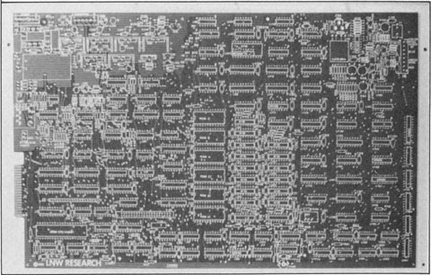
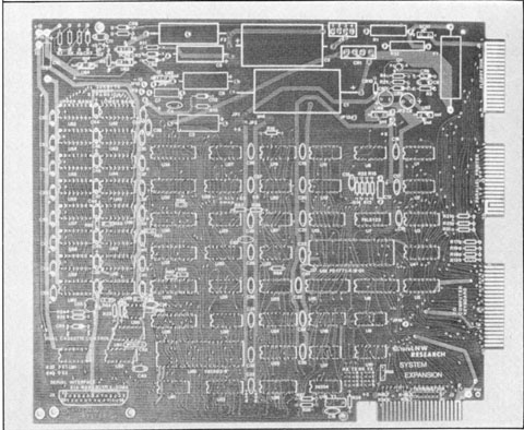
I selected the full-blown semi-kit: printed circuit boards for the CPU sec- tion and an expansion interface ($90 and $85 with gold edge connectors), keyboard with numeric pad ($100), metal case ($85), three hard-to-find parts kits ($140 - more on that later), and a Level II ROM set ($120). The semi-kit total, with shipping, was about $640. To that total I had to add the ex- pense of a bucketful of my own parts and quite a few purchases, including capacitors, resistors, integrated circuits (48K of memory, too), regulators, diodes, transistors, sockets, and miscellaneous whatsises like fuse cases and wire clamps - the kind of stuff I always thought I had in my oversized junkbox, but when it came down to needing it, the cupboard was bare. This investment came to about $250 more, making the total kit cost about $900. This is at least $700 below an assembled LNW-80 ($1,600), or about the same as a TRS-80 Model III purchased at discount.

Before jumping in with the construc- tion, you might want to know what this LNW computer is. The manufacturer calls it a Model I/III-compatible micro- computer with added features. But the LNW-80 is both more and less than that. Model I/III users will find it very familiar, while first-time computer users will appreciate the wide range of features that TRS-80 owners have known for some time. But I’ll hold off listing these capabilities until I describe the assembly and operation of the computer. For the moment, consider that this machine contains just about every feature Model

LNW-80 kit
a worthwhile
endeavor


I owners have hoped for or modified their units to contain, and many of those the Model III should have had. In addition, high-resolution graphics (384 by 192) and color are standard.

In the next two columns, I’ll cover assembly and operation, plus some fixes, to the LNW-80. In addition to running through the assembly of the machine, I will also present a few quick and easy modifications that will facil- itate using some of the LNW’s special features.

Before I begin, readers, please take note: I’m going to sound harsh in some of my criticisms of LNW Research, their documentation and support, and some aspects of the computer itself. Nevertheless, I purchased the LNW be- cause I had the opportunity to use one

and became convinced that it is a very good computer. Notwithstanding the amount of grief involved in the assembly of the machine, my views about its quality have not changed.

Opening the Box

The first surprise is how heavy the delivered box is - $11.17 worth of UPS up here to New England. Although most of the weight turns out to be the heavy metal case, that heftiness gave me a reassuring feeling about the whole system. I’m always a sucker for appearances, but this hunch was a good one. The case is 1/16-inch solid steel, painted cream white, and packed in plenty of scratch protection. A few bags of screws dropped out, and un- derneath was a pair of printed circuit boards.

All the integrated circuits - the so- called hard-to-find parts kit - were thrown ignominiously into a plastic bag, with the static-sensitive ones bundled into little aluminum foil globs. The five-pound transformer had fortunately been packed well and pre- vented from crushing the other parts. The keyboard is complete and also well packed; the connector survived un-

All LNW parts assembled
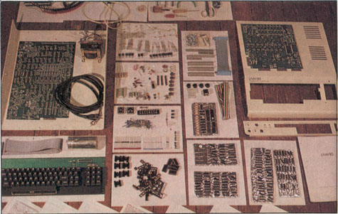
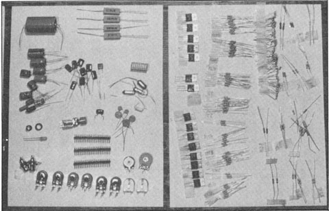
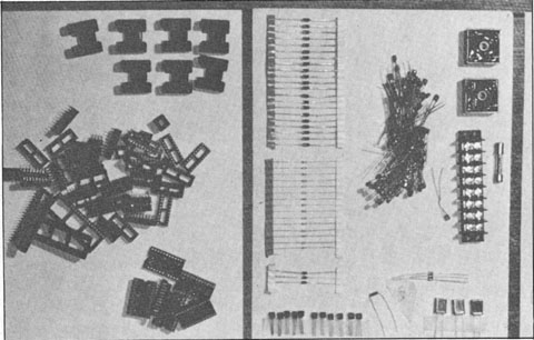
Photo l. All the parts assembled for a complete LNW-80 kit. Clockwise from back: necessary tools; case top and expansion PC board; case back; manuals; foil trays of integrated circuits; sockets and heat sinks; keyboard, cable, and power-supply capacitors; main PC board, cord, transformer, in case bottom; at center are remaining small parts and hardware; at very bottom (just visible) are sche- matic sheets.

356 . 80 Micro, October 1982
bent. A hefty sheaf of documentation rose out of the packing material. Another chunk of case fit into the bot- tom of the box. Photo 1 shows the complete parts in the semi-kit, together with all the extra parts purchased to complete the computer. The next photos are close-ups of the carefully manufactured printed circuit boards. Just a few of the hundreds of extra parts purchased for the kit are shown in Photo 3.

Long ago I learned the lesson that it’s important to read an entire con- struction manual before attempting to build a kit, so I held myself back from tearing into the pile of parts with my soldering iron ablaze, and sat down in a comfortable chair with some Dewars and the LNW manual. I was soon con- fronted with one of the biggest docu- mentation cop-outs I have ever read: The purchaser of the LNW-80 is assumed to have a certain degree of ability in assembling electronic -equip- ment. Therefore, a detailed step-by- step assembly manual containing top- ics, such as how to install a resistor, transistor, or IC, will not be discussed. What the assembly instructions will in- clude are general and specific construc- tion hints that we felt would be useful in making your LNW-80 board as easy and simple to build as possible.

Okay, says I, that’s on the inside edge of reasonable. However, LNW’s defini- tion of construction hints is to tell you only how to wire parts of the machine that otherwise defy logical construc- tion. The entire assembly and testing section for this $900 project is just 10 pages of dot-matrix printing, vague de- scriptions, and a few sketches. Com- pared with the detailed, clear, and care- fully written documentation of the Archbold speed-up kit for the Model I, this assembly book is an inexcusable jumble: no photos, messy sketches, and dot-matrix printing. There is not a sin- gle valuable troubleshooting hint in the manual. Here’s an example: "Turn sys- tem on and measure the following volt- ages... (voltage chart)... Turn power off and solder all power-supply jumpers indicated below... (jumper chart)... reaply (sic) power and measure all sup- ply voltages as you first did. After all voltages are present, you can install all ' components that you are to use."

What if it doesn’t come up with the right voltages? Where do you look? How do you start? Don’t look for help

in Section 8 (Circuit Description). This is so cursory (10 pages including an ex- pansion bus pinout and abbreviated memory map) as to be useless. My 12-volt supply didn’t work; here’s what I found in their description: “CR15 rec- tifies the AC signal which is then filtered by C121. Q4 regulates the voltage to + 12 volts. If the voltage at JP9 exceeds 13 volts, CR11 will begin to conduct. While the gate of Q6 remains un- changed, the anode will begin to rise above the gate voltage. This will cause Q6 to begin conducting and result in turning SCR2 on. F2 will then open. The + 12 volts are used for both the LNW-80 and the Expansion Board." My fuse was intact, yet there was no
LNW80 bare main board
LNW80 bare expansion interface board
Photo 2. LNW-80 blank printed circuit boards. (a) Main CPU and high-resolution board; (b) expan- sion interface with gold edge connectors. The board are settings on the case bottom and top, respec- tivily.

80 Micro, October 1982 . 357


+ 12 volts. Yeah, I found it, but not because I knew what the gobbledygook above was supposed to mean.

Okay, time to back up and sum- marize the manual’s problems:

  • It is incomplete in the description of the computer, assembly instructions, and technical data about the machine’s operation and circuitry.
  • It doesn’t match the LNW-80 since the computer has been changed but the documentation hasn’t. The errata don’t cover all the changes.
  • It specifies parts that physically do not fit on the printed circuit board - es- pecially the variable resistors and
capacitors.
  • It’s unclear and not particularly literate (I’ve been misunderstood before when I said that about other publica- tions. I don’t mean literary; I merely mean knowing how to spell, punctuate, and produce a reasonably complete sentence.)
  • It is disorganized; even the errata ap- pear in several places. There is no logical flow for the builder, no clear breakdown for repairs, and no specifications or tolerances.
  • LNW releases itself from respon- sibility by implication; that is, LNW Research continues to ship a manual
labeled "preliminary" even though it is dated March 1981 (and the expansion board documentation dated October 1979).

The LNW manual makes several as- sumptions that, two years after the Model I’s demise, no longer make sense (if they ever did). The first and most problematic is that the user must al- ready know how to operate a TRS-80. There is no Basic manual, no instruc- tions for operation, no specifications for the language, not even a list of com- mand words or errors. The first-time user of this machine will be lost. Beyond that, all the notions common to TRS-80 users are assumed - precision, speed of operation, even how to enter a pro- gram. And what of the confusion that results when a user releases the shift or caps lock and still sees uppercase let- ters‘? Although the keyboard implies it, there is no lowercase driver in the Basic! To use the LNW-80, then, it becomes imperative to have the background, manuals, and instruction books for Radio Shack’s TRS-80. This is an eco- nomical cop-out for LNW (even if they did intend to be a‘software copycat of the Model I), yet it is a serious disservice to the LNW-80 buyer.

There’s one more problem, and this one’s a little more far-reaching. You simply cannot build this kit unless you have both good tools and test equip- ment, and that means more than a pocket voltmeter. It means you will probably need a temperature-controlled soldering unit (or at least an often- cleaned, low-wattage iron with several tips), a good multimeter (preferably a digital one), and an oscilloscope. I was scrupulous about assembling this LNW-80 (and it’s far from the first computer I’ve put together) and it still would not function correctly when it was finished. The scope was essential.

Neither the advertisements nor the manuals suggest that this is a tough pro- ject. It is. And if you think that you can. get started assembling the computer when it arrives, you’re wrong; LNW Research sells only a hard-to-find parts kit, not the whole works. Although the kit does include some esoteric parts, it seems to be mostly a random collection . of what was out of stock in southern California when LNW made up its list. Be prepared to search for a high-speed CPU, odd regulators and zener diodes, plus a host of obscure capacitors - tan- talums, variables, high-capacitance

LNW80 bare main board
LNW80 bare expansion interface board
Photo 3. Just a few of the extra parts that must be purchased before the kit can be built. (a) Hundreds of resistors, capacitors, voltage regulators, switches, variable resistors, LED, etc.; (b) bridge reticeivers, bypass capacitors, diodes, sockets, heat sinks.

358 . 80 Micro, October 1982


types, and odd sizes. In fact, it took more than a dozen telephone calls to round up the parts that I didn’t already own – although more than half of those “hard to find” parts I did have. Still curiously missing was an RGB ROM (for high-resolution color graphics), although assembled LNW-80s are being shipped with this ROM; instead, an NTSC ROM was included. Calls to LNW for information about the RGB ROM were fruitless. Total time from receipt of LNW-80 kit to final rounding up of all remaining parts: 18 days.

First Steps

Once all the parts were at hand, I was more than ready. I commandeered an entire room of the house. Cats out.

I gave the boards another visual in- spection, since the last thing I wanted to troubleshoot was a bashed trace on the board. I looked carefully, with a bright light and a magnifying glass, but the blearies got to me and I gave up. Bad move; more later on the problems caused by that single incomplete trace.

The 0.1 mF bypass capacitors went in first, since they were the smallest (and

prettiest) parts. I got a good quantity price on tiny Blue Max capacitors, since nearly 200 are used in the full system (Photo 4). Then the resistors went in - a real pain. These things are numbered counterclockwise from the middle-left side of the board... mostly. Finding the last 20 or so was improbable madness, since they are scattered out of order around the board. Some resistor num- bers are left over because they are not used, contributing to the confusion (Photo 5). Finally, I inserted the re- maining capacitors, which were also scattered about. Total time for resistors and capacitors: four hours. After that 18-day wait, though, the energy level was high. I forced myself to take a break, then jumped into install- ing the sockets. Okay folks, that’s - no kidding - 1,848 solder points. That’s two hours of continuous soldering, not counting the sneezing fits from solder
Installation of capacitors
Photo 4. Installation of the capacitors. High-quality Blue Max miniature PC capacitors are used, although any 0.1 mF disks are adequate.
Power supply corner main board
Photo 5. Resistors, regulators, capaciters, and connectors installed. Sockets will go in next.

80 Micro, October 1982 . 361


flux smoke. But nevertheless, so far, so good. I put in miscellaneous parts such as crystals, vokage regulators, small connectors, and a DIP switch for select- ing Level II or other ROMs.

The miniature glass diodes can be dif- ficult to install because they are very small and their glass bodies break. So you might take the advice of an author years ago in Popular Electronics (I’ve long forgotten who; if you recall, let me know). Lay the diodes against the point

of a pencil and bend each lead around the pencil. It forms a kind of spring to protect the diode from snapping when installing it, plus gives the added bonus of providing a natural heat-sink during soldering (see Fig. 1).

After hours o f little stuff, I decided to put some large hardware together. Iron- ically, this is the best documentation in the manual. The case assembly, trans- former and keyboard installation, back panel, and various sockets and recep-

tacles (darn! gotta buy a power cord, too!) fit perfectly in place. An automo- tive hose clamp made an excellent holder for the big capacitor, and for safety I purchased heavy bridge rec- tifiers and bolted them to the case. I slipped the PC boards in place just to admire my handiwork and went to bed.

Next time: Completing the assembly, testing, the disappointing LNW key- board bounce, the RFI question, com- parisons with Models I/III, the success of the 4 MHz speed, questions of weight md heat, screen deglitching, thoughts about reliability, easier dealings with high-resolution graphics, and a sche- matic map to keep you from tearing them up in frustration.
Diode install
Fig. 1. Save installation of small glass diodes. (a) Bend the leads around a pencil lead; (b)insert the finished diode easily on the board, providing both stress protection and heat-sinking.

358 . 80 Micro, October 1982