| IBM PC RT 6151 |
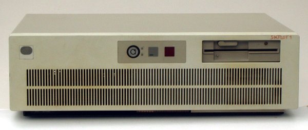 |
The case is very similar to the original PC AT case. The main difference is the two-digit hex post display.
|
| IBM PC RT CPU |
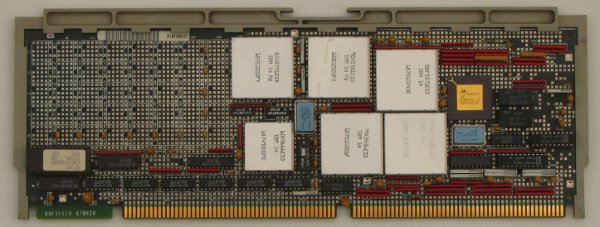 |
The aluminium coveraging of chips is typically for IBM designs. These chips make up the RT processor. The board contains some MMI PAL-logic, a Motorola support chip and a boot EPROM. Below are the other special cards for the PC-RT. The I/O; disk, display, network and serial ports are provided by 'normal' 8- or 16-bit ISA cards.
|
| IBM PC RT CO-processor |
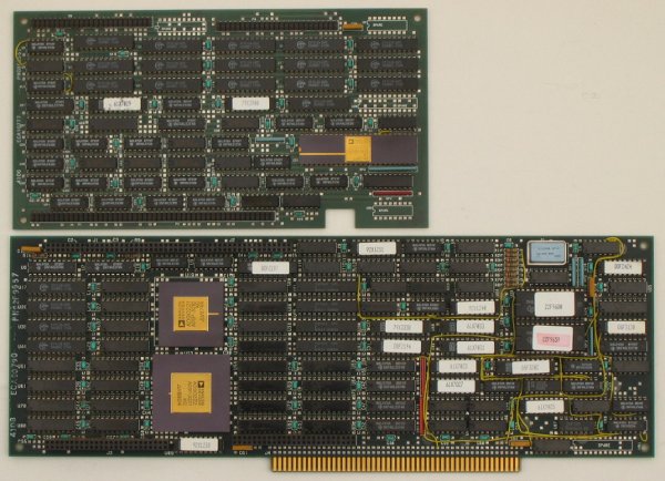 |
This board set is an option. It contains two Analog Devices chips; an ADSP-3210 (floating point multiplier and ALU) and an ADSP-3221 ().
The extension board contains several fast (cache like) RAM chips.
|
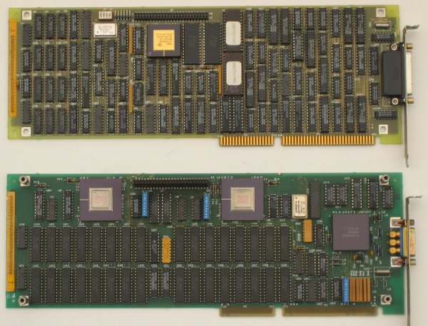
| IBM PC RT RAM board |
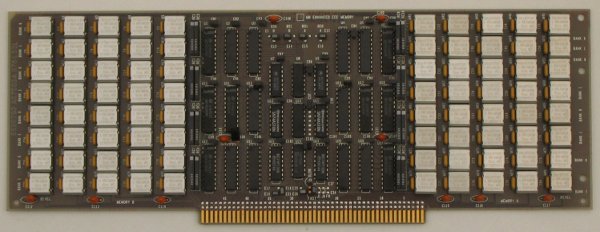 |
Here also the typically IBM chip housing. The early IBM PS/2s also used this type or RAM. This board could be either 4 or 8 MByte.
|
| FDC/ESDI board & network board |
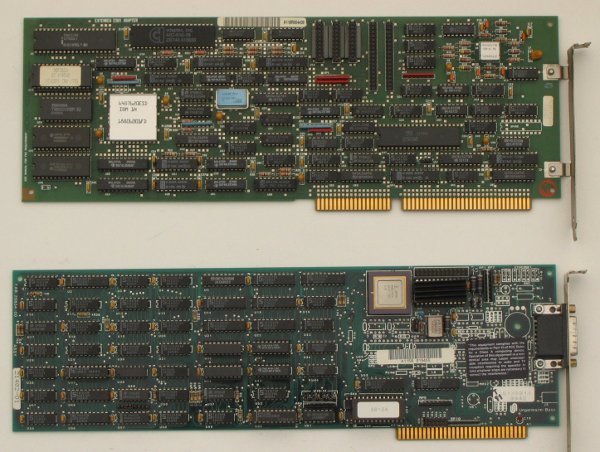 |
At the top the FDC and ESDI harddisk controller, at the bottom an Ungermann-Bass network adapter.
|
| Megapel Display Adapter |
 |
These boards form one adapter. Best put into slot 2 and 3 (from the left, slot 1 being only 8 bits). The proper display is the IBM 5081 Display monitor. Output is RGB, sync on green, H:63.36 kHz, V:60Hz. DIP switch 3 controls the CGA emulation.
|
| Keyboard/Mouse ports |
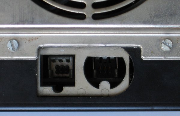 |
Very weird connectors. The actual pins are standard 0.1" pins for both keyboard and mouse, but the shape of the holes made
connecting foolproof. An improvement to the DIN-connectors used for the original PC/PC XT and PC/AT, but not yet the standard of
PS/2. The mouse is the left port, the keyboard right.
|
| Keyboard/Mouse connectors |
 |
A bit dirty, but the construction is clear. The keyboard is left, the mouse right.
|
| Mouse internals |
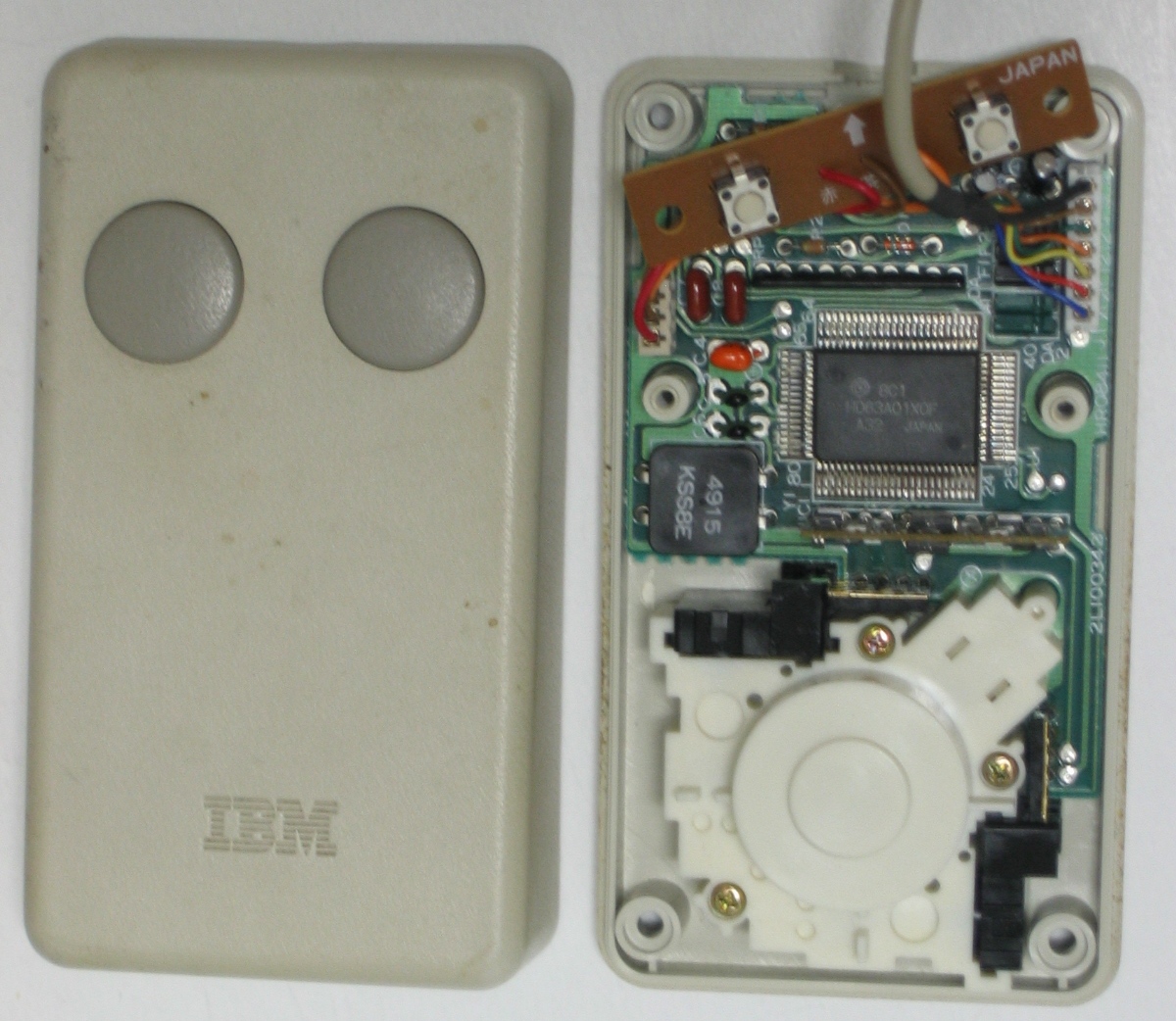 |
The mouse interior. A complete HD6303A01XOF processor (derived from the 6801) and a propriatairy protocol.
  IBM RT mouse
Part No OOF2383

As seen into the plug (female)
 ___________
|           |
|| 1  3  5 ||
 | 2  4  6 |
 |_________|


  plug wire   J1   function
    1 (green)  5 = signal ground.
    2 (blue)   1 = Transmit to device.
    3 (orange) 4 = +12 Volts
    4 (yellow) 3 = -12 Volts
    5 (brown)  6 =  +5 Volts
    6 (red)    2 = Receive from device.
      (black)  7 = protective ground
|