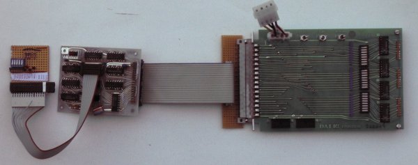
At the right the DAI DCE experimenter board, which exercises the 24 lines of the RWC bus. Connected to it is a RWC-to-DCE bus converter. Then the Memocom MDCR interface board. At the other side of the MDCR cable, at the far left is an custom MDCR simulator, with LEDs for the four control lines and power, and DIP switches for the five status lines.
The DCE-MDCR interface uses the DCE-bus in a way that does not interfere with RWC cards, but apart from card adressing, the pins are used differently. The interface has two modes: id and control/status. Up to four interfaces can be connected, all reside inside the address space of one RWC card. The two switches on the interface select the drive address.
In id mode, a bit pattern is put on six bits of PORT 2, and two of those bits reflect the remaining two bits (one direct, the other inverted). In control/status mode, PORT 0 contains the MDCR status bits and PORT 2 sets the control bits.
In the lists below, off = low, on = high, x = don't care.
PORT 1 is used for the RWC-card select. It is hardcoded to address 0 using bits 4 to 7. The bits 2 and 3 select the drives. Bit 1 switches between control/status and id mode. Bit 0 must be on.
PORT 1 addressing:
B7     off
B6     off
B5     off
B4     off
B3     x   (address bit 2)
B2     x   (address bit 1)
B1     sel*
B0     on

sel:
 on   control/status address
 off  id address
PORT0 reflects the MDCR status bits. Bits 2 to 4 are not used and always on.
PORT 0 status:
B7     RCD
B6     WEN
B5     CIP
B4     on
B3     on
B2     on
B1     BET
B0     RDA
PORT 2 sets the MDCR control bits. Bits 4 to 7 are not used.
PORT 2 control:
B7     x
B6     x
B5     x
B4     x
B3     WCD
B2     WDA
B1     FWD
B0     REV
The pattern on PORT 0 is fixed in id mode.
PORT 0 id:
B7     on
B6     on
B5     on
B4     on
B3     off
B2     off
B1     on
B0     off
In ID mode PORT 2 is split into an input nibble and an output nibble. Of each only two bits are used. Bits 0 and 2 are input, bits 5 and 7 are output. Bit 7 is equal to bit 2 and bit 5 is the inverse of bit 0. The bits 4 and 6 are high-impedance (tri-state).
PORT 2 id:
B7     B2
B6     on
B5     not B0
B4     on
B3     on
B2     x
B1     on
B0     x
Updated: 2012-05-19