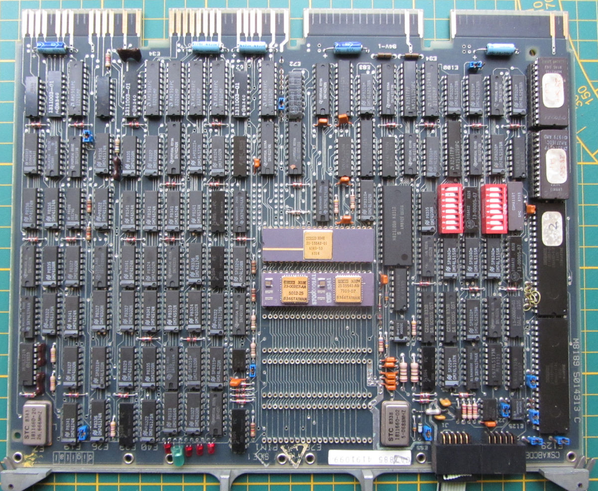
M8189 CPU
I found out the hard way that having both a 50Hz clock at the BEVNT pin and jumper J11 grounded (connected to J10), doesn't work very well for running small programs from ODT. The programs usually don't have interrupt handling, so maximum run-time is 40 ms, when the interrupt ends it all. This is the reason for the hardware console panel LTC switch.
The KDF11B M8189 is described in the Digital_Microcomputer_Products_Handbook_1985, 4.1- (p.63-). The used configuration is in this text file
- Digital_Microcomputer_Products_Handbook_1985, 4.1- (p.63-)
- KDF11-B CPU Module User's Guide EK-KDFEB-UG
- PDP-11/23B Mounting Box Technical Manual EK-23BMB-1M
- PDP-11/23B Mounting Box User's Guide EK-23BMB-UG
- KDFI1-BA Field Maintenance Print Set MP-01236-00
- 11/23-B Field Maintenance Print Set MP-01234-00
- 11T23-B Field Maintenance Print Set MP-01235-00
- EB-19402-20 PDP11 Processor Handbook PDP11-04-24-34A-44-70
- KDF11B-BH ROM V1.0 Boot/Diag ROM set for the M8186 (works for M8189, but uses BDV11 preset switches)
- KDF11B-BJ ROM V1.1 Boot/Diag ROM set for the M8189
M8067 RAM
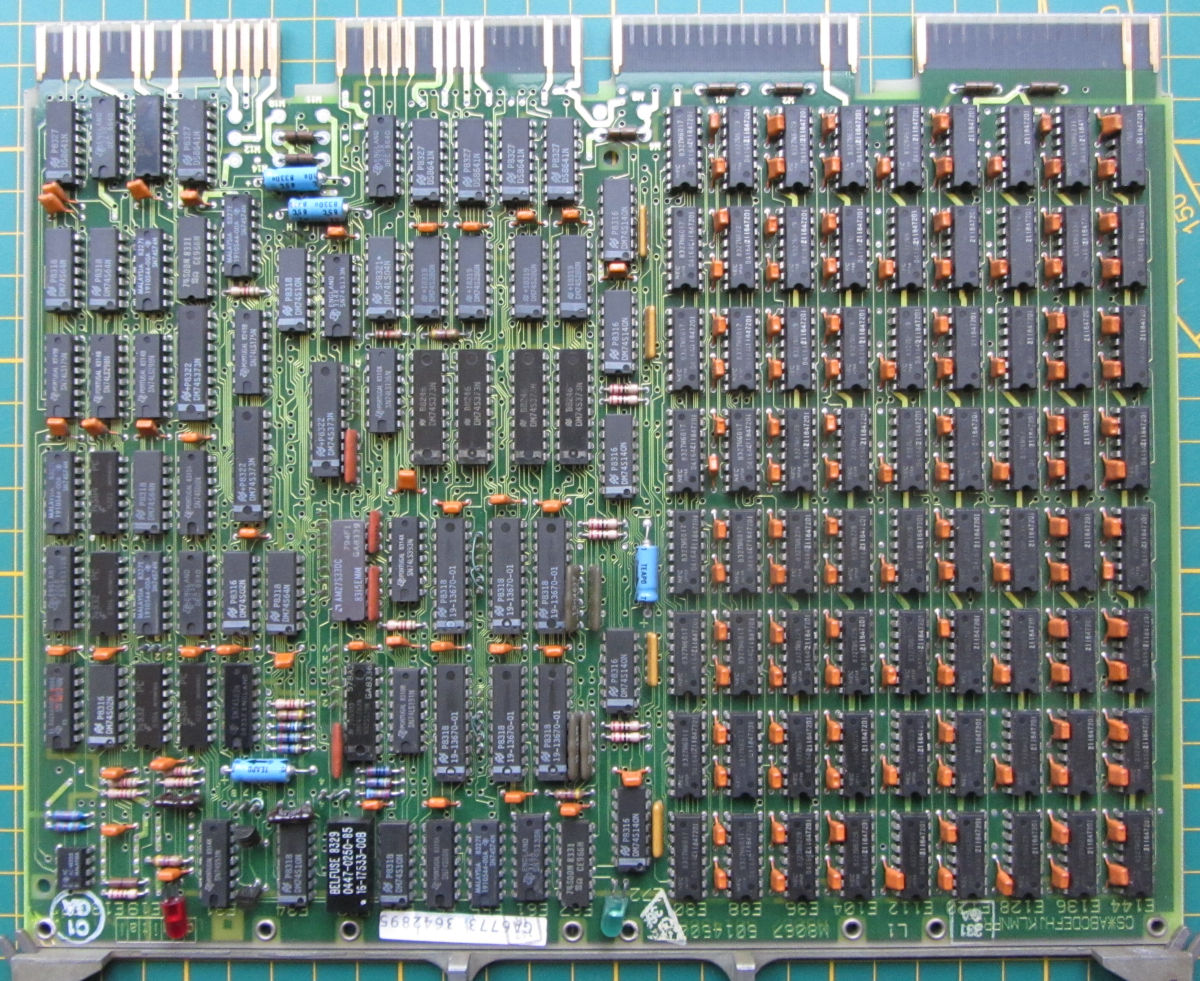
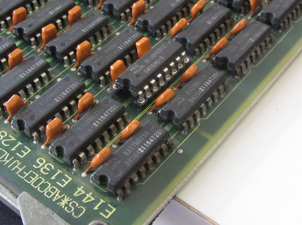
This dynamic RAM board has 9 * 8 NEC4164: 256 kWord with parity. This is more than enough for running (small) programs.
Once the Boot/Diagnostics ROMs started working, it reported RAM errors:
ERR 3 MEMORY FAULT
 ADDRESS  EXPECTED   ACTUAL
00400000    177400   177600   FF00 FF80 > D7 bit stuck on
00400000    052525   052725   5555 55D5 > D7 bit stuck on
00420000    177400   177600
00420000    052525   052725
....
With the User Guide available, this appeared to be bit 7 of row 1, IC 135. Replaced this with a NEC D4164-3 (150 ns), and the errors were gone.
M8067 MSV11-PL 9 * 8 NEC4164: 256 kWord:
- Digital_Microcomputer_Products_Handbook_1985, 14.1- (p.201-)
- MSVII-P User's Guide
- MSVII-P Field Maintenance Print Set MP-01239-00
- MSV11 Diagnostic Documentation Kit ZJ246-RZ
M7551 RAM
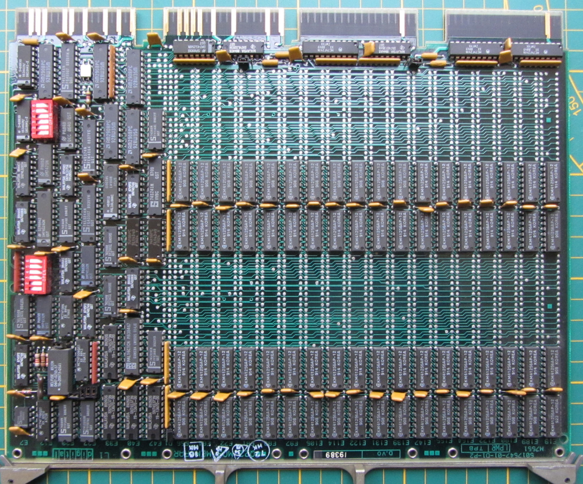
This dynamic RAM board has 18 * 4 KM41256AP: 2048 kWord and default it isn't installed.
M7551 MSV11-QB:
- Digital_Microcomputer_Products_Handbook_1985, 15.10- (p.220-)
- MSV11-QA Memory User's Guide EK-MSV1Q-UG
- MSV11-Q Field Maintenance Print Set MP-01931-00
- MSV11 Diagnostic Documentation Kit ZJ246-RZ
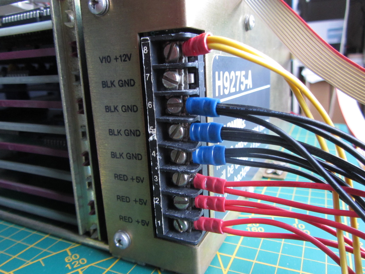
The rack is powered with a modified standard PC-power supply. Too light for a full rack, but ok with two boards and fans (7.7 A on 5V).
The enclosure for the backplane and rack is still under construction. The main controls are routed to a custom board, providing the 50 Hz, ENABLE/HALT switch and delays for BDCOK and BPOK. A switch to disable the 50Hz to BEVTN is to be added.
The H9275-A backplane is very straight forward, with just a serpentine pattern for all slots:

The PDP-11/23Plus front panel is wired to the backplane via a 9-pin connector. This is the routing, derived from the documentation:
H9275-A J2 to LSI-11 backplane to M8189 schematic page mapping:
----------    ----------------    --------------------
BDCOK         BA1                 M8189-0-K2, C7
BPOK          BB1                 M8189-0-K3, B6
BHALT         AP1                 M8189-0-K3, B2
BEVNT         BR1                 M8189-0-K8, A8
SRUN          AF1,AH1             M8189-0-K1, D1
The SRUN signal might be routed to the upper Qbus slot only.

This is the unfinished rack containing the H9275A backplane, a ATX power supply, the control panel and the serial ports (console (SLU1) and SLU2 (can be TU58 port).